Air and contaminant isolation and removal apparatus and method

a technology of air and contaminant isolation and removal apparatus, which is applied in the direction of filtration separation, multi-stage water/sewage treatment, separation process, etc., can solve the problems of preventing the polymer from bonding with the water molecule, and the unsatisfactory configuration of pollution control

Active Publication Date: 2011-03-10
PURADYN FILTER TECH
View PDF16 Cites 11 Cited by
  • Summary
  • Abstract
  • Description
  • Claims
  • Application Information

AI Technical Summary

Problems solved by technology

This creates an undesirable configuration for pollution control.
The presence of valent c

Method used


Image

  • Air and contaminant isolation and removal apparatus and method
  • Air and contaminant isolation and removal apparatus and method
  • Air and contaminant isolation and removal apparatus and method

Examples


Embodiment Construction

[0074]For purposes of description herein, the terms “upper”, “lower”, “left”, “rear”, “right”, “front”, “vertical”, “horizontal”, and derivatives thereof shall relate to the invention as oriented in FIG. 1. However, one will understand that the invention may assume various alternative orientations and step sequences, except where expressly specified to the contrary. Therefore, the specific devices and processes illustrated in the attached drawings, and described in the following specification, are simply exemplary embodiments of the inventive concepts defined in the appended claims. Hence, specific dimensions and other physical characteristics relating to the embodiments disclosed herein are not to be considered as limiting, unless the claims expressly state otherwise.

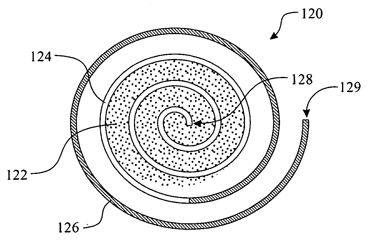
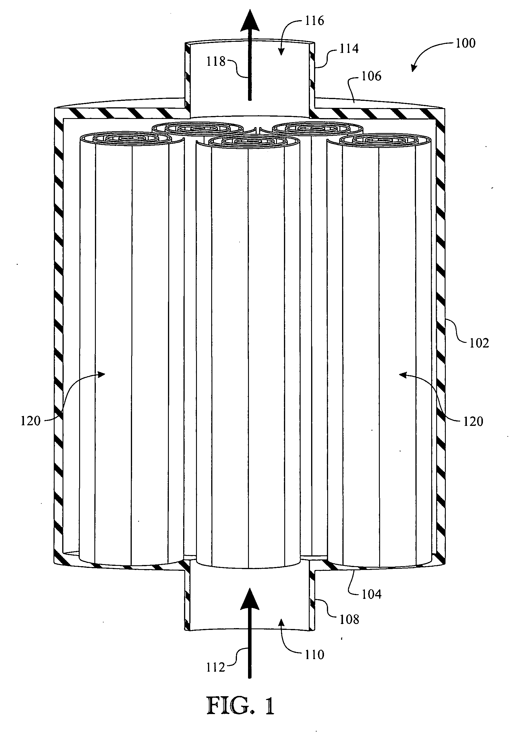
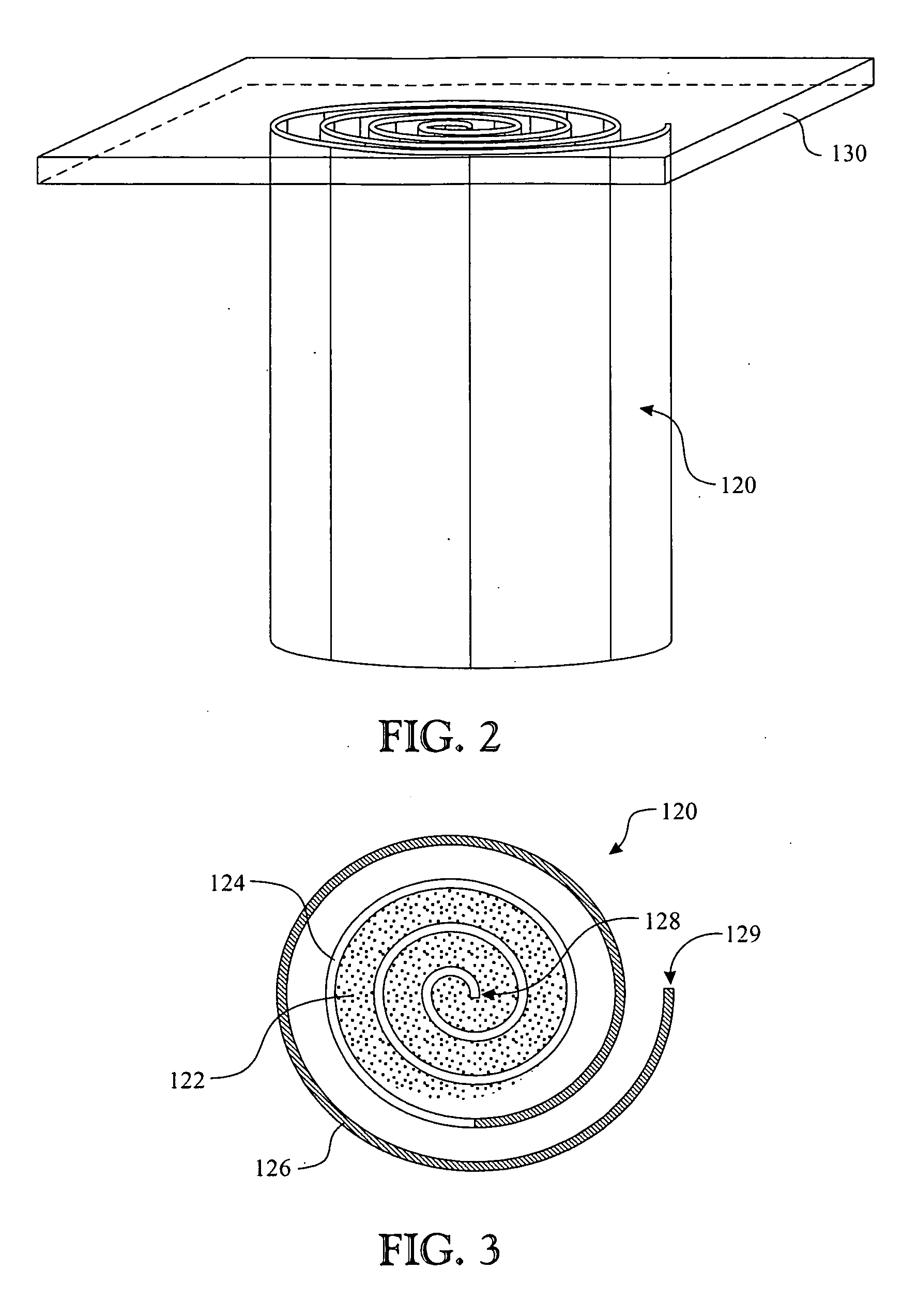
[0075]A moisture-extracting device, generally referenced as 100, is presented in a sectioned elevation view illustrated in FIG. 1. The moisture extracting device 100 is defined as a chamber formed having a filter housi...


PUM

PropertyMeasurementUnit
Volumeaaaaaaaaaa
Water absorptionaaaaaaaaaa

Abstract

A lubricant reclamation system having a moisture absorbent cartridge (140). The cartridge (140) is fabricated placing a Superabsorbant Polymer (SAP) (142) within a boundary of polyester mesh (143). Moisture is extracted from a lubricant or other fluid and absorbed by the SAP. The moisture latent SAP bonds to the polyester mesh (143), potentially turning into a gel. A layer of polypropylene sorbent (144) is placed about the exterior of the boundary material (143), ensuring any moisture remains exterior to the sorbent layer (144). A resin layer can optionally be placed within a fluid flow following the discharge from polypropylene sorbent extracting aerosol from within the lubricant and as a barrier of detrimental ions with an exchange of beneficial ions. The entire cartridge can be placed within an enclosure or pouch body (162). The body (162) is designed to expand, accommodating a resultant increase in SAP volume. The cartridges can be integrated into filters comprising commonly known filtration elements.

Description

BACKGROUND OF THE INVENTION[0001]1. Field of the Invention[0002]The present invention relates to a fluid purification system and more specifically to a device and method for removing aerosols and contaminants from fluids such as lubricants, fuels, and the like.[0003]2. Discussion of the Related Art[0004]This invention relates to fluid purification devices and method, which are preferably used in conjunction with engines using lubricating oils or hydraulic systems. More particularly, the present invention provides several unique oil / lubricant treatment configurations creating a unique system for fluid reconditioning.[0005]Oil reclamation devices are known to incorporate an evaporator head having a heat-transmitting member mounted within a cavity. The heat-transmitting device can incorporate baffles to form a baffled evaporator chamber.[0006]Oil filters are provided in a variety of form factors and materials. Common filters comprise a filtering medium disposed within a canister and se...

Claims


Application Information

Patent Timeline
IPC IPC(8): B01D36/00B01D17/00B01D29/00B01D29/07
CPCB01D17/10B01J20/106B01D36/003B01D53/0407B01D2253/202B01D2257/80C10M175/005B01D15/00B01J20/16B01J20/18B01J20/261B01J20/267B01J20/28035B01J2220/68B01J20/165B01J20/2804B01J20/2805B01D27/08
Inventor JACOBS, WILLIAM A.JACOBS, BRIAN A.SANDLER, ALAN
Owner PURADYN FILTER TECH
Why Eureka
Try Eureka