Image quality monitor for digital radiography system

a digital radiography and image quality technology, applied in image enhancement, fire alarms, instruments, etc., can solve the problems of affecting the portability of such a device, the large amount of complex miniaturized circuitry of portable dr detectors, and the number of pixels found to be defectiv

Active Publication Date: 2011-03-10
CARESTREAM HEALTH INC
View PDF9 Cites 39 Cited by
  • Summary
  • Abstract
  • Description
  • Claims
  • Application Information

AI Technical Summary

Benefits of technology

[0017]It is an advantage of the present invention that it tracks both correctable and non-correctable pixel-based imaging anomalies for a portable DR detector.

Problems solved by technology

Inevitably, some number of pixels are found to be defective.
Even some tethered detectors may be somewhat portable; however, such devices typically have thick, rigid covers protecting the sensor and scintillating screen from any outside forces.
However, there are some disadvantages related to the portability of such a device.
Unlike film and CR cassettes, a portable DR detector contains a considerable amount of complex miniaturized circuitry.
Rough handling of such a device, for example, can lead to some abrasion damage across the sensor surface, thus increasing the likelihood of defects and requiring additional calibration cycles in order to update the defect map.
Moreover, with increasingly more compact packaging, environmental factors such as temperature variation can also cause the detector to need more frequent calibration.
In addition, normal and rough handling of the detector can result in subtle motion of the scintillating screen relative to the sensor panel, resulting in localized changes in gain.
These gain changes, which can be corrected by performing a gain calibration, have the appearance of misregistration artifacts.
Because of the factors discussed above, the required intervals between calibration procedures, needed for maintaining suitable image quality, are less predictable for fully portable detectors.
However, this type of arbitrary interval negatively impacts productivity.
Calibration procedures require radiology staff time and attention and each calibration reduces the overall utilization time of the DR detector.
This procedure may detect the need for calibration, but effectively disrupts operator workflow and increases access time for obtaining the current fully corrected clinical image.
This disruption and time loss may be unacceptable in many clinical environments.
In critical situations, such as in the emergency room or intensive care unit, for example, valuable time would be lost.
This method, although it may prove successful enough for a non-portable, mounted DR detector, falls short of what is needed for fully portable digital X-ray detectors.
Such methods fail to distinguish between misregistration artifacts, which can be eliminated by performing a gain calibration, and truly defective pixels that need to be added to the defect map.
As a result, the detector would eventually exceed the threshold for the number of allowable defects and would have to be taken out of operation.
In summary, while there are some indications that conventional pixel defect detection methods may perform well enough when used within more permanent DR detector installations, these same methods do not appear to successfully address particular requirements of the portable DR detector.
It has been found, for example, that conventional methods fail to distinguish between correctable misregistration problems that can be characteristic of portable devices, and truly defective pixels.
This shortcoming limits the effectiveness of conventional approaches and makes these known solutions less desirable for the more rigorous requirements of the portable DR detector.

Method used


Image

  • Image quality monitor for digital radiography system
  • Image quality monitor for digital radiography system
  • Image quality monitor for digital radiography system

Examples


Embodiment Construction

[0034]The following is a detailed description of the preferred embodiments of the invention, reference being made to the drawings in which the same reference numerals identify the same elements of structure in each of the several figures.

[0035]The term “set”, as used herein, refers to a non-empty set, as the concept of a collection of elements or members of a set is widely understood in elementary mathematics. The term “subset” as used herein refers to a non-empty subset of a set having one or more members. For a set S, a subset may comprise the complete set S (improper subset) or may have fewer members than the complete set S (proper subset).

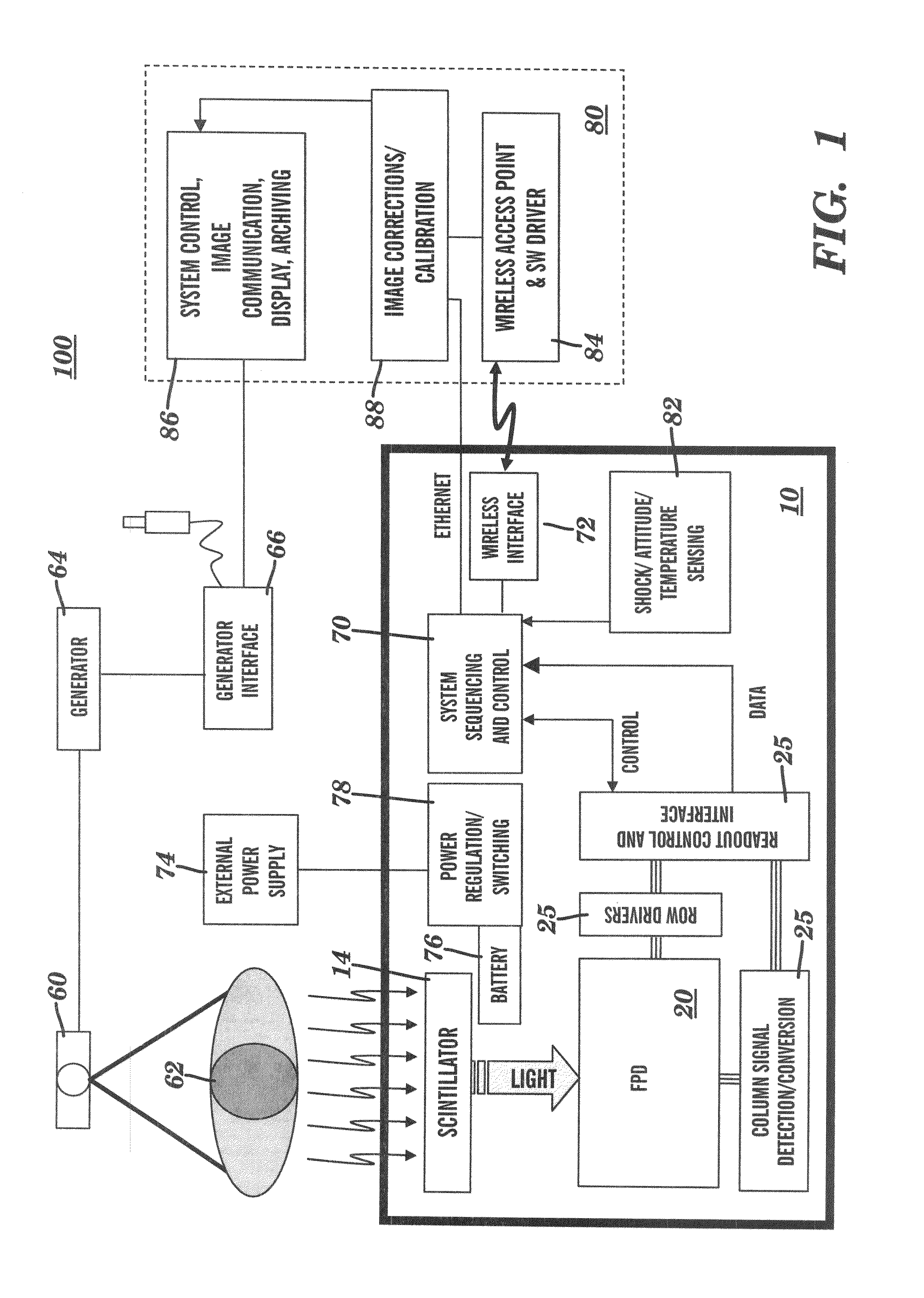
[0036]A DR detector system and particular requirements for a portable. DR detector are described with reference to FIG. 1. The schematic diagram of FIG. 1 shows, at a high level, the basic architecture of a radiographic system 100 that uses a portable DR detector 10. An x-ray source 60, with a supporting generator 64 and a generator interface 6...


PUM


Abstract

A system for monitoring the state of calibration of a digital x-ray detector having a solid state sensor with a plurality of pixels, a scintillating screen and at least one embedded microprocessor, the system having means for capturing a digital image and a computer operable during normal diagnostic use of the detector, in cooperation with at least one embedded microprocessor, for performing pixelwise computations on the image and calculating a misregistration metric indicative of movement of the solid state sensor relative to the scintillating screen. A defect metric indicative of abnormal properties of pixels in the solid state sensor is calculated. It is then determined whether one or both of the misregistration metric and the defect metric exceeds a respective, preselected threshold value. The user of the system is alerted to conduct a calibration of the detector when either one or both of the respective threshold values have been exceeded.

Description

CROSS-REFERENCE TO RELATED APPLICATIONS[0001]Priority is claimed to U.S. Provisional Application Ser. No. 61 / 240,373, titled IMAGE QUALITY MONITOR FOR DIGITAL RADIOGRAPHY SYSTEM, by Topfer et al, filed Sep. 8, 2009.FIELD OF THE INVENTION[0002]This invention generally relates to digital radiography (DR) imaging and more particularly relates to a method for monitoring DR detector performance in order to identify the need for recalibration.BACKGROUND OF THE INVENTION[0003]Digital Radiography (DR) detectors directly transform received exposure energy to digital image data. These detectors commonly contain an array of light sensitive picture elements, or pixels, arranged in a matrix of rows and columns and a scintillator, consisting of a material, such as gadolinium oxisulfide, Gd2O2S:Tb (GOS) or cesium iodide, that absorbs x-rays incident thereon and converts the x-ray energy to visible light photons. In some configurations, the scintillator is in direct contact with the light sensitive...

Claims


Application Information

Patent Timeline
Patent Type & Authority Applications(United States)
IPC IPC(8): G08B21/18G06K9/68G06K9/00
CPCA61B6/00A61B6/585G06K9/036H04N5/367G06T2207/10116H04N5/32H04N5/3655G06T7/0004G06V10/993H04N25/673H04N25/68
Inventor TOPFER, KARINSCOTT, RICHARD T.WOJCIK, TIMOTHY J.
Owner CARESTREAM HEALTH INC
Why Eureka
Try Eureka