Tool head for use in a multiaxis machine, multiaxis machine having such a tool head, and use of such a machine

a multi-axis machine and tool head technology, applied in the direction of driving apparatus, attachable milling devices, manufacturing tools, etc., can solve the problems of affecting the reliability or precision of the machine, the inability to ensure the capacity of the machine, and the high cost of such specialized machines, so as to achieve the effect of not affecting the accuracy of the machine and being more flexible to us

Inactive Publication Date: 2011-03-10
KLINGELNBERG AG
View PDF12 Cites 10 Cited by
  • Summary
  • Abstract
  • Description
  • Claims
  • Application Information

AI Technical Summary

Benefits of technology

[0009]The most important advantage of the invention is seen in that a corresponding specialized machine equipped with the tool head according to the invention is more flexibly usable. In spite of the corresponding structural changes of the machine, the precision properties are not negatively impaired.
is seen in that a corresponding specialized machine equipped with the tool head according to the invention is more flexibly usable. In spite of the corresponding structural changes of the machine, the precision properties are not negatively impaired.

Problems solved by technology

The costs of such specialized machines are frequently relatively high.
It is sometimes viewed as a disadvantage of these specialized machines that their capacity can only be ensured if large piece counts of identical or similar workpieces are to be processed.
It can occur that the add-ons or alterations obstruct the actual use of the machine in the original specialized area, or the reliability or precision of the machine is impaired.

Method used


Image

  • Tool head for use in a multiaxis machine, multiaxis machine having such a tool head, and use of such a machine
  • Tool head for use in a multiaxis machine, multiaxis machine having such a tool head, and use of such a machine
  • Tool head for use in a multiaxis machine, multiaxis machine having such a tool head, and use of such a machine

Examples


Embodiment Construction

[0029]Terms are used in connection with the present description which are also used in relevant publications and patents. However, it is to be noted that the use of these terms is only to serve for better understanding. The ideas according to the invention and the protective scope of the patent claims are not to be restricted in their extent by the specific selection of the terms. The invention may be readily transferred to other term systems and / or technical fields. The terms are to be applied accordingly in other technical fields.

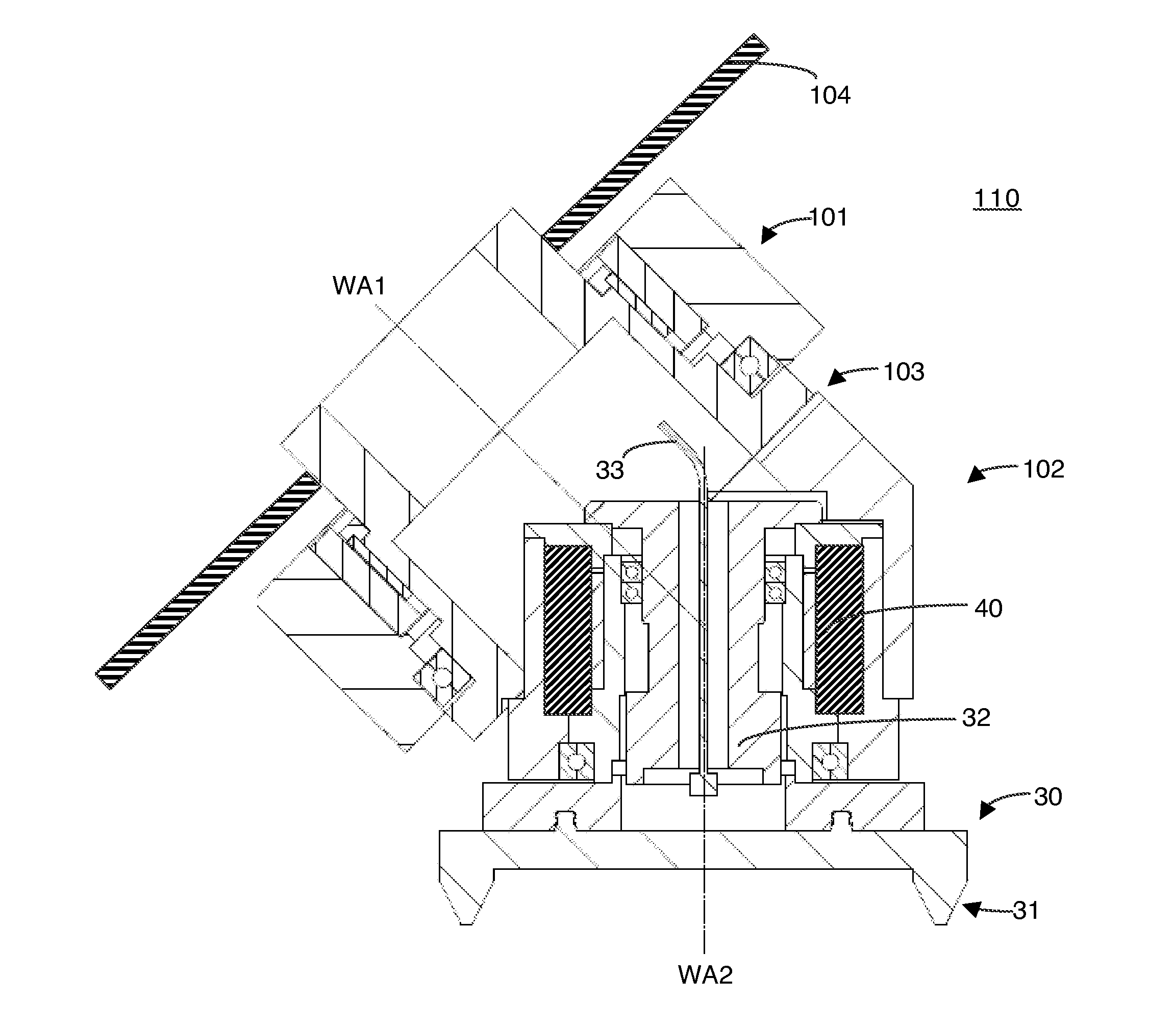
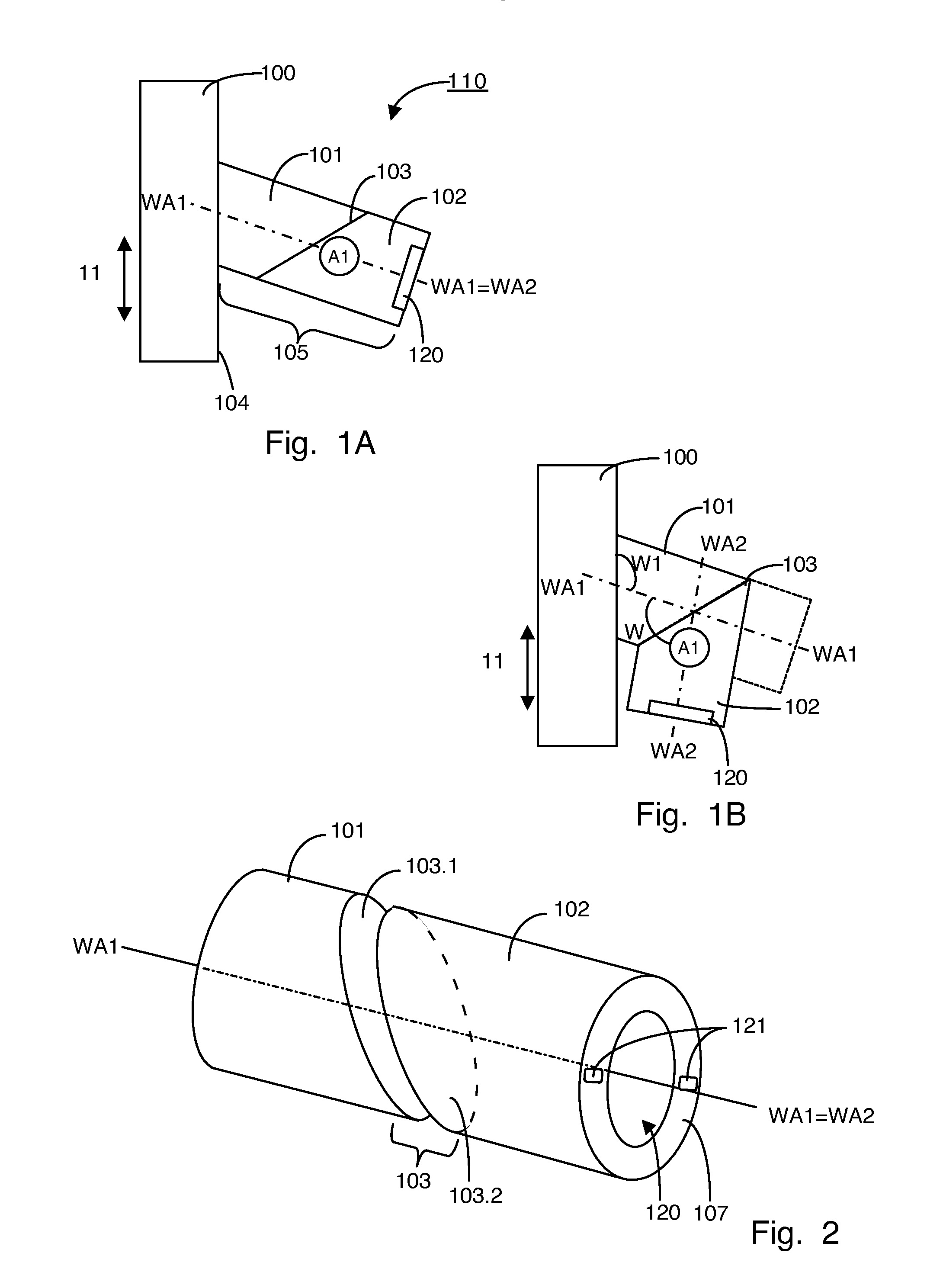
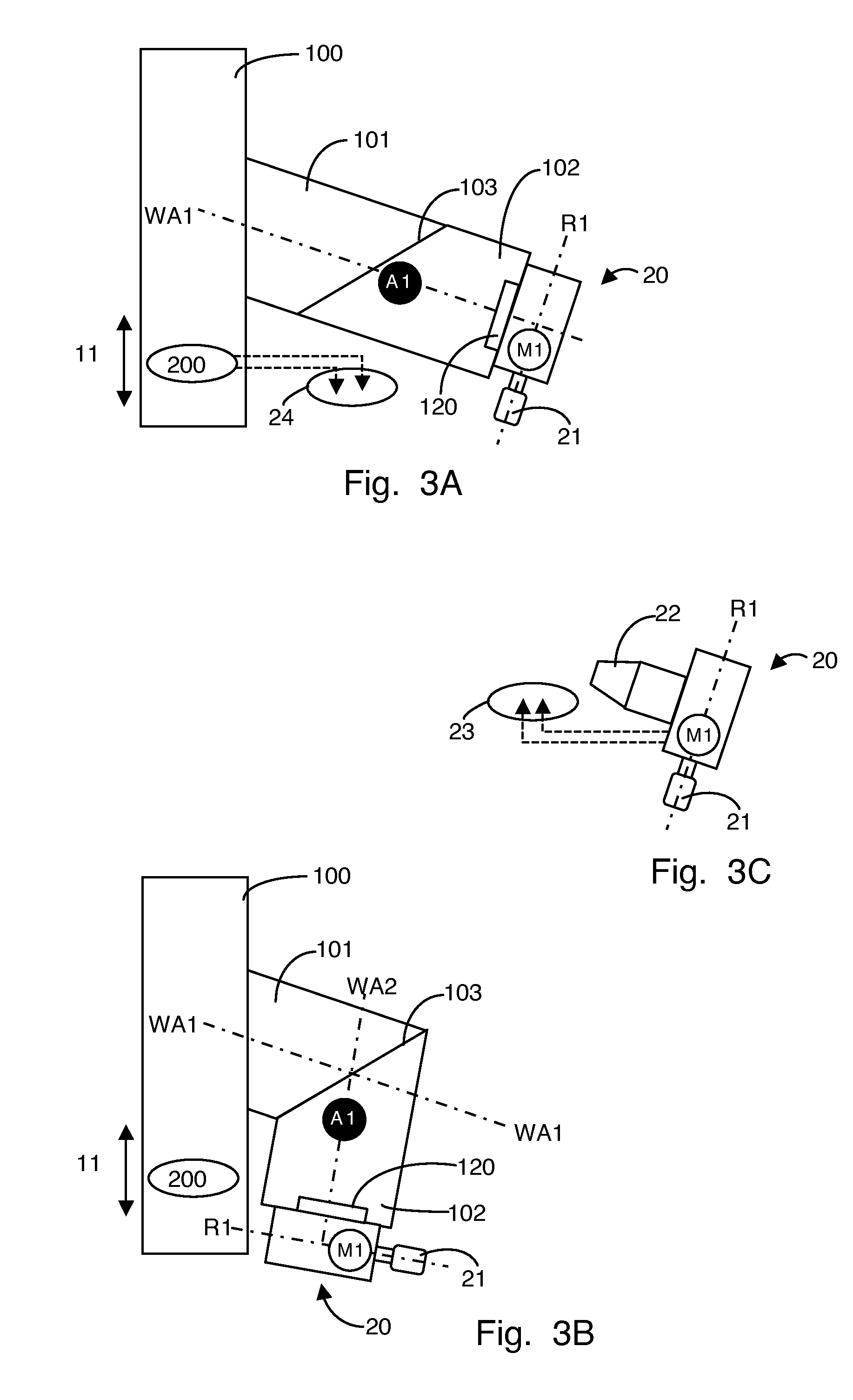
[0030]The invention relates to a novel tool head 110, which is shown in two extreme positions in FIGS. 1A and 1B. The tool head 110 is especially designed for use in a multiaxis machine 100. The machine 100, which is preferably a multiaxis, NC-controlled machine, is only shown as a block element in FIGS. 1A to 9.

[0031]The tool head 110 comprises a spindle body 105, which has two elements or assemblies 101, 102, as schematically indicated in FIGS. 1A and 1...


PUM

PropertyMeasurementUnit
angleaaaaaaaaaa
angle of inclination W1aaaaaaaaaa

Abstract

Tool head (110) for use in a multiaxis machine (100), the tool head (110) comprising a spindle body, which has two elements (101, 102). These elements (101, 102) are rotatably connected with one another via a corresponding coupling (103), the first element (101) having a first longitudinal axis (WA1) and the second element (102) having a second longitudinal axis (WA2), which are transferable from a stretched position into an angled position depending on the rotational position. A first drive (A1) is seated in or on the spindle body. A receptacle device (120) is provided, which is situated on the second element (102). This receptacle device (120) is used for fastening a motor spindle (20), a motor (M1), which is integrated in the motor spindle (20), being able to be supplied with power via the second element (102) and via electrical connection means of the receptacle device (120). The receptacle device (120) is also used for fastening a milling tool (30), which is drivable using the first drive (A1).

Description

CROSS REFERENCE TO RELATED APPLICATION[0001]The present application claims the priority of European Patent Application No. 09169933.0, which was filed on 10 Sep. 2009 and is incorporated herein by reference.FIELD OF THE INVENTION[0002]The object of the invention is a tool head for use in a multiaxis machine, a multiaxis machine having such a tool head, and the use of such a machine.BACKGROUND OF THE INVENTIONPrior Art[0003]There is an entire array of specialized machines, which are designed and optimized for the processing of greatly varying materials and workpieces. The costs of such specialized machines are frequently relatively high. It is sometimes viewed as a disadvantage of these specialized machines that their capacity can only be ensured if large piece counts of identical or similar workpieces are to be processed.[0004]There is an increasingly a demand to improve the capacity of the corresponding machines in that the machines are made more flexibly usable by add-ons or alter...

Claims


Application Information

Patent Timeline
Patent Type & Authority Applications(United States)
IPC IPC(8): B23C1/12B23Q5/04
CPCB23Q5/045B23Q5/10Y10T409/309296Y10T409/308232Y10T409/309408
Inventor BRIEDEN, CHRISTIANVON DER MARK, BERND
Owner KLINGELNBERG AG
Why Eureka
Try Eureka