Rifle scope with adjustment stop

a technology of a scope and an adjustment stop, which is applied in the direction of telescopes, instruments, weapons, etc., can solve the problems of easy loss of zero point when elevation is dialed, insufficient markings, and easy loss of the adjustment track of the user to return to zero point, so as to improve the appreciation of the contribution of the art

Active Publication Date: 2011-03-17
SHELTERED WINGS
View PDF6 Cites 70 Cited by
  • Summary
  • Abstract
  • Description
  • Claims
  • Application Information

AI Technical Summary

Benefits of technology

This patent describes an improvement to a hunting gun's scope called a "rifle scope with adjustment stop." The new version includes several improvements: it has a fixed reference point on its outer edge (called a "stop surface") where other parts can attach or move without affecting the main part of the scope. It also uses a special mechanism to secure one of these attachment points (a "turret") to prevent accidental movement during use. These changes make the scope easier to install and use, and help ensure accurate shots when hunting.

Problems solved by technology

The technical problem addressed in this patent text is the difficulty and potential error in adjusting the elevation turret of a rifle scope to compensate for the effect of bullet drop at longer ranges. The conventional turrets lack a zero stop mechanism, making it easy for the user to lose track of the adjustment and over-adjust. The patent proposes a new and improved rifle scope with an adjustment stop to prevent excessive adjustment of the turret beyond a preset amount.

Method used


Image

  • Rifle scope with adjustment stop
  • Rifle scope with adjustment stop
  • Rifle scope with adjustment stop

Examples


Embodiment Construction

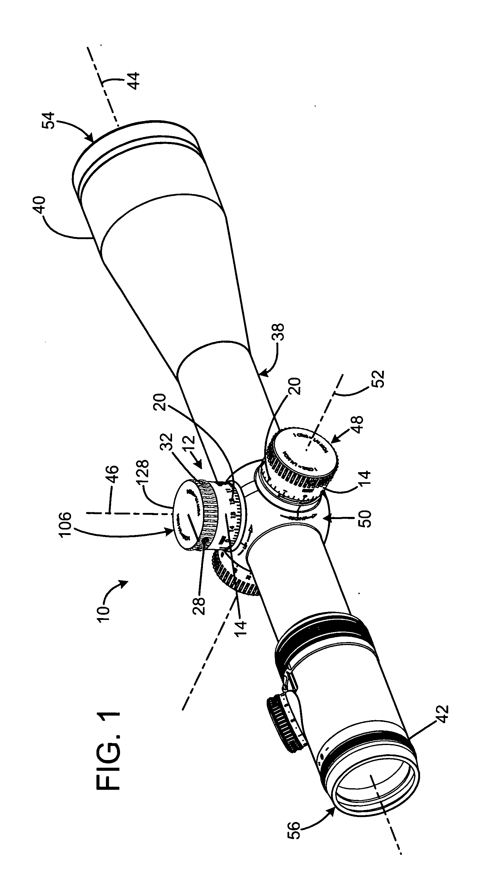
A preferred embodiment of the rifle scope with adjustment stop of the present invention is shown and generally designated by the reference numeral 10.

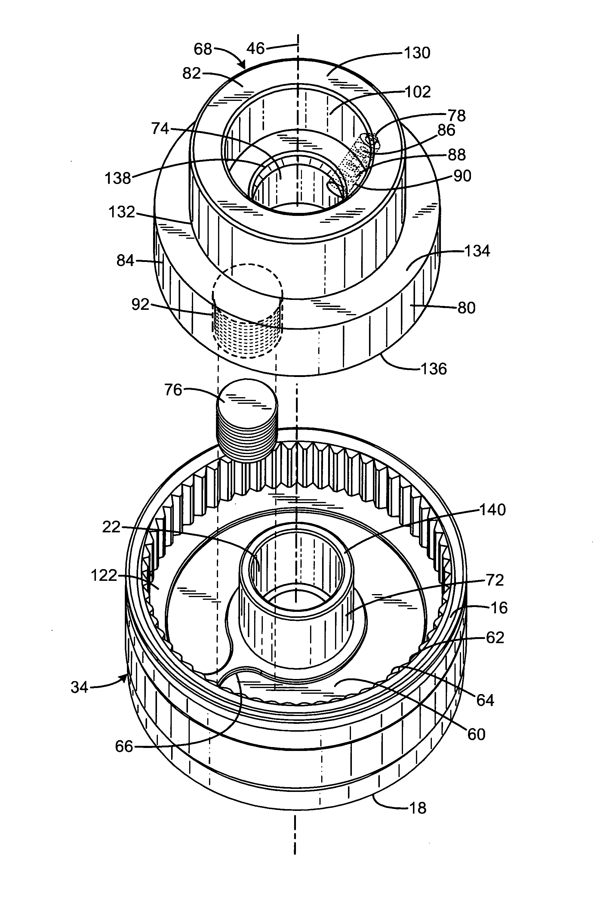
FIG. 1 illustrates the improved rifle scope with adjustment stop 10 of the present invention. More particularly, the rifle scope 10 has a scope body 38 that encloses a movable optical element 126 (shown in FIG. 8), which is an erector tube. The scope body 38 is an elongate tube tapering from a larger opening at its front 40 to a smaller opening at its rear 42. An eyepiece 56 is attached to the rear of the scope body, and an objective lens 54 is attached to the front of the scope body. The center axis of the movable optical element defines the optical axis 44 of the rifle scope.

An elevation turret 12 and a windage turret 48 are two knobs in the outside center part of the scope body 38. They are marked in increments by indicia 20 on their perimeters 14 and are used to adjust the elevation and windage of the movable optical element for po...


PUM


Abstract

Rifle scopes with adjustment stops include a scope body, a movable optical element defining an optical axis enclosed by the scope body, and a turret having a screw operably connected to the optical element for adjusting the optical axis in response to rotation of the screw. The turret has a stop element selectably engaged to the screw. The body defines a stop surface positioned for engagement by the turret stop element to limit rotation of the screw, such that the relative position at which the stop element is secured to the screw defines a zero position of the screw and the movable optical element. The stop element is held against the stop surface by an indexing portion while the relative position at which the stop element is secured to the screw to define the zero position is determined.

Description


Claims


Application Information

Patent Timeline
Owner SHELTERED WINGS
Why Eureka
Try Eureka