Ignition device attachment structure for internal combustion engine

Active Publication Date: 2011-03-17
HONDA MOTOR CO LTD
View PDF13 Cites 2 Cited by
  • Summary
  • Abstract
  • Description
  • Claims
  • Application Information

AI Technical Summary

Benefits of technology

[0007]The present invention has been made in view of the above-mentioned situations and aims to provide an ignition devic

Problems solved by technology

For example, an obstacle encountered when the ignition device is inserted may l

Method used


Image

  • Ignition device attachment structure for internal combustion engine
  • Ignition device attachment structure for internal combustion engine
  • Ignition device attachment structure for internal combustion engine

Examples


Embodiment Construction

[0026]The present invention will now be described in detail with reference to the accompanying drawings, wherein the same reference numerals will be used to identify the same or similar elements throughout the several views. It should be noted that the drawings should be viewed in the direction of orientation of the reference numerals. An embodiment of the present invention will hereinafter be described with reference to the drawings.

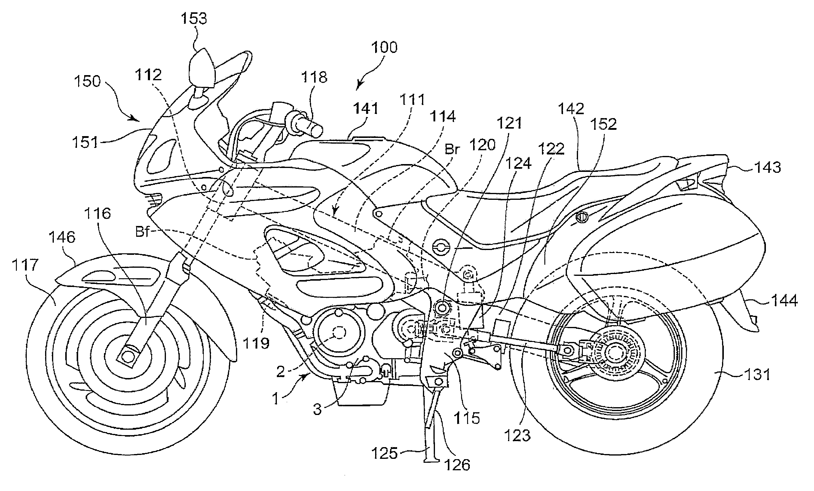
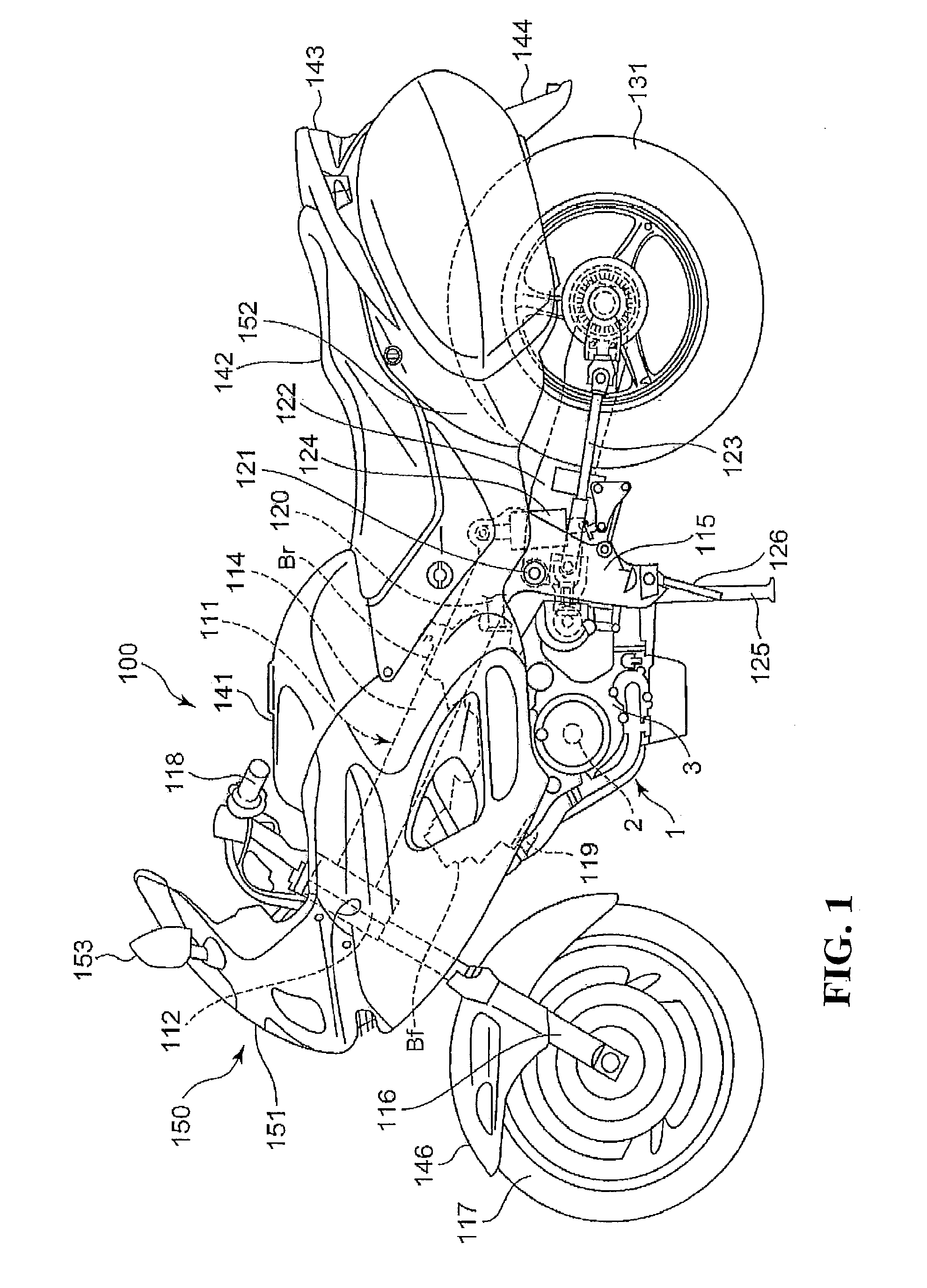
[0027]FIG. 1 is a lateral view of a motorcycle to which an ignition plug attachment structure for an internal combustion engine according to an embodiment of the present invention is applied. The directions such as front and rear or back, left and right, and upside and downside in the following description are based on a vehicle body.

[0028]A body frame 111 of a motorcycle 100 includes a head pipe 112 located in the front portion of the vehicle body; a pair of left and right main frames extending rearward from the head pipe 112 to the center of the vehic...


PUM


Abstract

An ignition device attachment structure for an internal combustion engine includes an ignition plug tube inserted between a cylinder head cover and an ignition device insertion hole formed in a cylinder head of the internal combustion engine. The ignition plug tube bulges from an upper end of the ignition plug tube to an intermediate portion of the ignition plug tube on a lateral surface of the ignition plug tube.

Description

CROSS-REFERENCE TO RELATED APPLICATIONS[0001]This nonprovisional application claims priority under 35 U.S.C. §119(a) on Patent Application No. 2009-215034, filed in Japan on Sep. 16, 2009, the entirety of which is incorporated herein by reference.BACKGROUND OF THE INVENTION[0002]1. Field of the Invention[0003]The present invention relates to an ignition device attachment structure, and more particular, to an ignition device attachment structure for an internal combustion engine.[0004]2. Background of the Invention:[0005]There has been known an internal combustion engine in which an ignition plug tube is inserted between an ignition device insertion hole formed in a cylinder head and a cylinder head cover (see e.g. Japanese Patent Laid-Open No. 2007-327378). In this internal combustion engine, an ignition plug as the ignition device is inserted into the ignition plug tube and then inserted into the ignition device insertion hole.[0006]In the above-mentioned traditional configuration,...

Claims


Application Information

Patent Timeline
IPC IPC(8): H01T13/08F02F1/42
CPCF02P13/00
Inventor TERADA, KOJIKISAICHI, TORUKAWAKUBO, SHINSUKE
Owner HONDA MOTOR CO LTD
Why Eureka
Try Eureka