Sputtering device

a technology of sputtering device and sputtering chamber, which is applied in the direction of electrolysis components, vacuum evaporation coating, coating, etc., can solve the problems of negative impact on efficiency, workpiece exposure to less than ideal environmental conditions, contamination and/or spontaneous oxidized film on workpieces

Inactive Publication Date: 2011-03-17
HON HAI PRECISION IND CO LTD
View PDF4 Cites 0 Cited by
  • Summary
  • Abstract
  • Description
  • Claims
  • Application Information

AI Technical Summary

Problems solved by technology

However, the coating process is prone to deteriorate due to transportation, thereby negatively impacting efficiency.
Furthermore, the workpieces are expo

Method used


Image

  • Sputtering device
  • Sputtering device
  • Sputtering device

Examples


Embodiment Construction

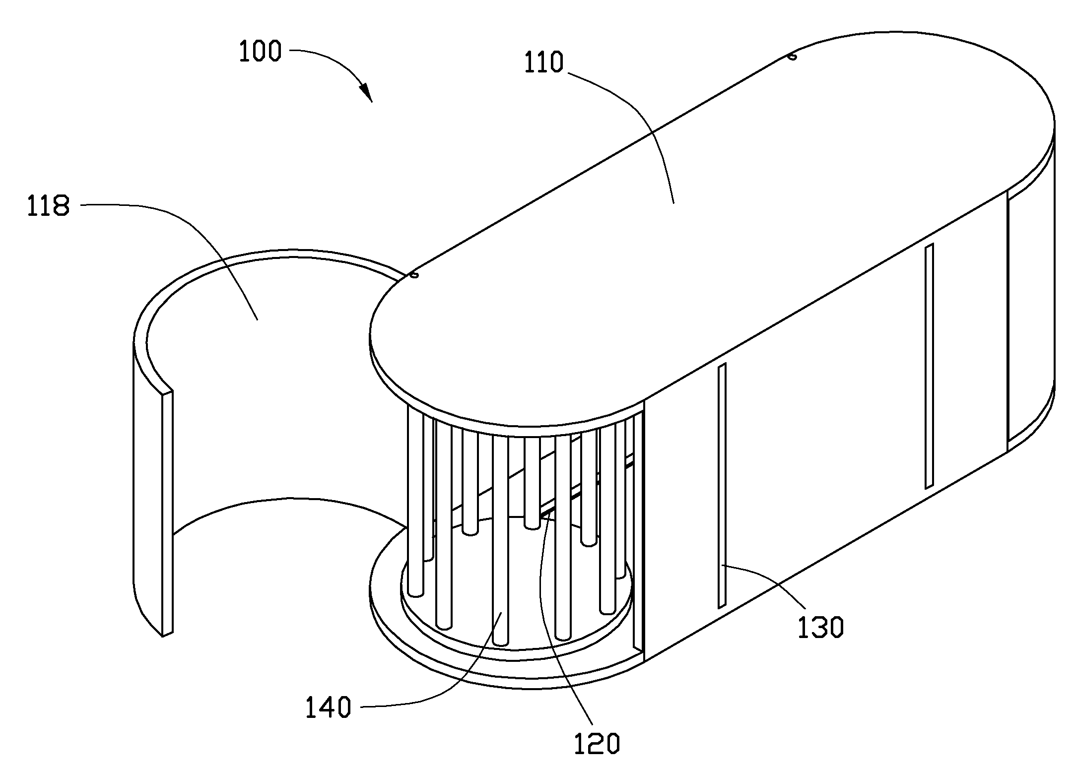
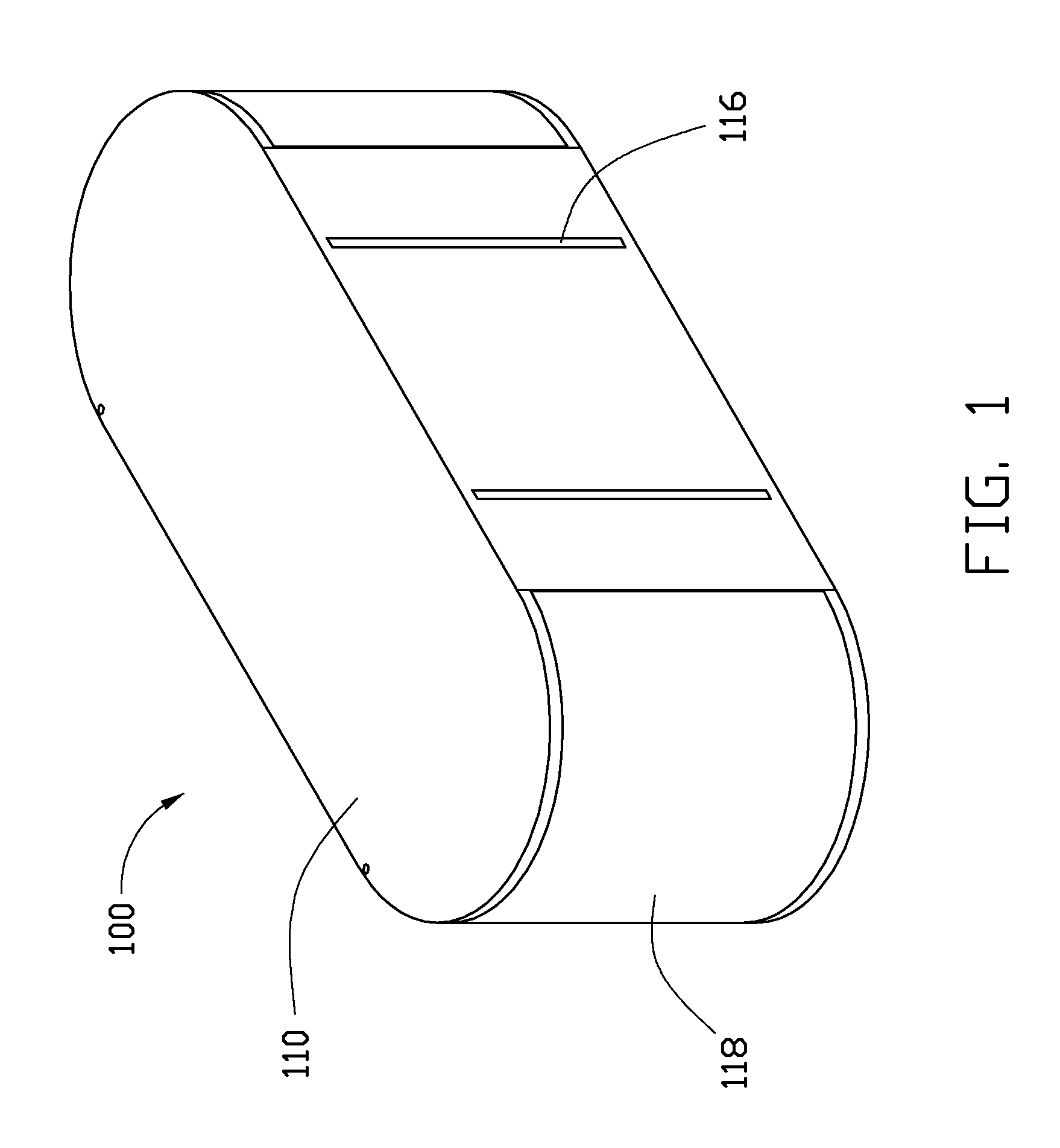
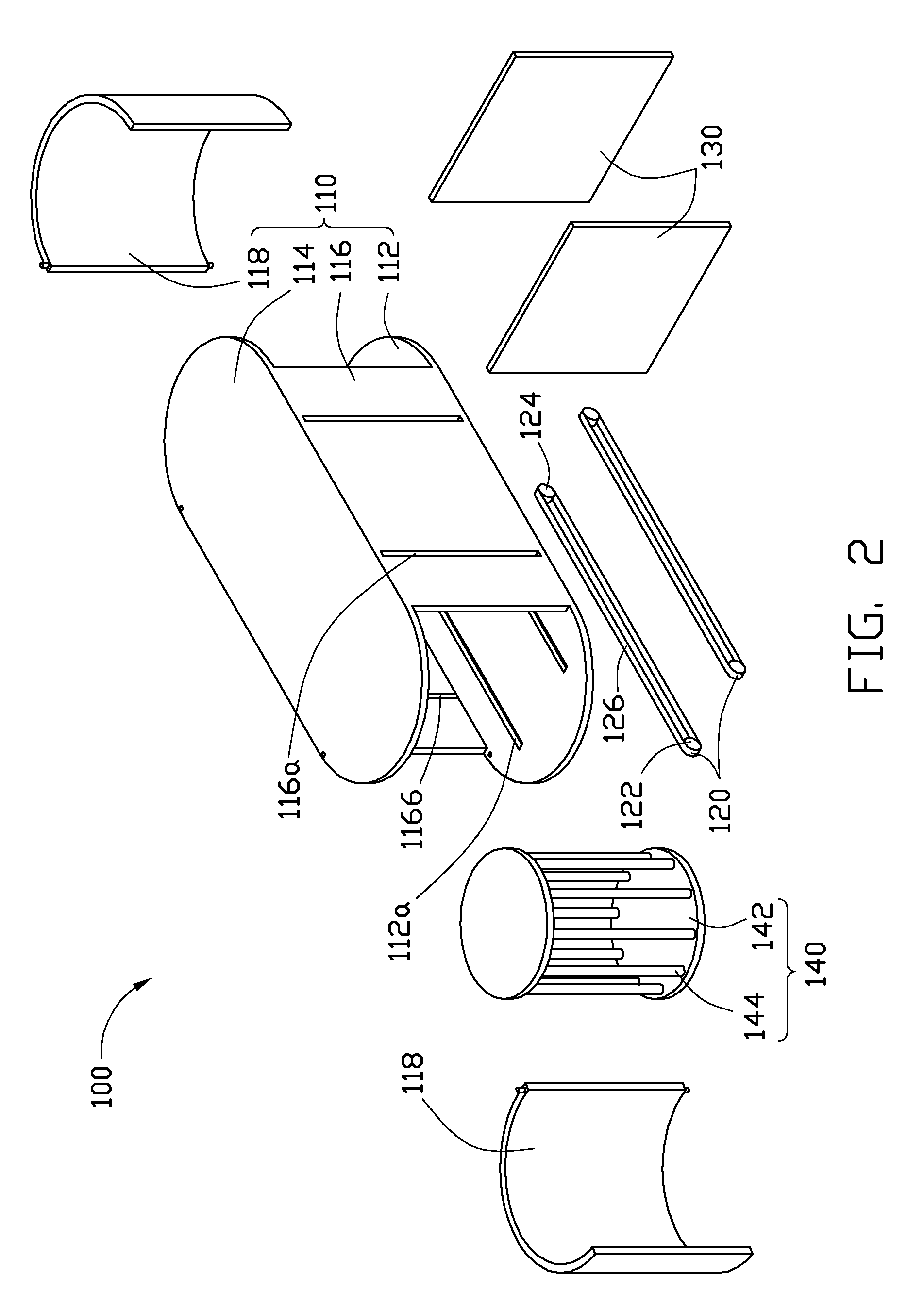
[0009]Referring to FIGS. 1 and 2, a sputtering device 100 according to an exemplary embodiment of the present disclosure is shown. The sputtering device 100 includes a housing 110, a pair of conveyors 120, two baffles 130, and a workpiece support 140. The housing 110 defines a chamber (not labeled) therein. The conveyor 120 and the workpiece support 140 are accommodated in the housing 110. The conveyor 120 is mounted on the bottom of the housing 110 for transporting the support 140 in the housing 110. The baffles 130 are slidably installed on the housing 110, provided for dividing the chamber of the housing 110 into a number of separated rooms. The baffles are slidable relative to the housing between a first position where the rooms are isolated and sealed by the baffles 130 from the others, and a second position where the rooms communicate with each other. The support 140 can be transported from one room to another by the conveyor 120.

[0010]The housing 110 has a rectangular box-lik...


PUM


Abstract

A sputtering device includes a housing, two baffles, a pair of conveyor, and a support. The housing includes a chamber therein. The baffles are slidably installed in the chamber of the housing to divide the chamber of the housing into a number of separated rooms where workpieces are treated. The baffles are slideable relative to the housing between a first position where the rooms are isolated and sealed by the baffles from others, and a second position where the rooms communicate with each other. The support is received in the housing. The pair of conveyor is mounted on the housing for transporting the support from one of the rooms to another.

Description

BACKGROUND[0001]1. Technical Field[0002]The disclosure relates to a coating device, and particularly, to a sputtering device.[0003]2. Description of Related Art[0004]In order to form multilayer films on workpieces, various sputtering devices are employed in coating treatment of workpieces. Commonly, sputtering devices are separated from each other. Accordingly, the workpieces to be processed need to be transported from one sputtering device to another. However, the coating process is prone to deteriorate due to transportation, thereby negatively impacting efficiency. Furthermore, the workpieces are exposed less than ideal environmental conditions leading among other things to contamination and / or spontaneous oxidized film being formed on the workpieces.[0005]What is needed is a sputtering device addressing the above-mentioned problems.BRIEF DESCRIPTION OF THE DRAWINGS[0006]FIG. 1 is an isometric view of a sputtering device according to an exemplary embodiment.[0007]FIG. 2 is an isom...

Claims


Application Information

Patent Timeline
IPC IPC(8): C23C14/50
CPCC23C14/34H01J37/34C23C14/568
Inventor WANG, CHUNG-PEI
Owner HON HAI PRECISION IND CO LTD
Why Eureka
Try Eureka