Microphone aperture

a microphone and aperture technology, applied in the direction of transducer casings/cabinets/supports, frequency/directivity obtaining arrangements, transducer circuits, etc., can solve the problems of instabilities in frequency-dependent directivity, poor directivity of transducers, and disadvantages of types

Active Publication Date: 2011-02-15
DPA MICROPHONES
View PDF11 Cites 10 Cited by
  • Summary
  • Abstract
  • Description
  • Claims
  • Application Information

AI Technical Summary

Benefits of technology

[0016]When the individual microphones of the microphone array are disposed depending on their frequency, and the band-pass filters are adjusted to the individual microphones with respect to their location in the array, frequency characteristic of the directivity is improved considerably, especially for low frequencies, but also for high frequencies.
[0026]Thus, even more directivities may be obtained without negative impact on the efficiency.

Problems solved by technology

The system shows a good directivity characteristic in the direction of the elongated array, however, a system of this type is disadvantageous in several ways.
The two major disadvantages are instabilities arising at the transition from one group to the next and thus instabilities arising in the frequency-dependent directivity characteristic because of the grouping of microphones according to frequencies.
As a result, the transducer has very distinct sidelopes, which means the directivity of the transducer is very poor.
The disclosed examples show a strong frequency dependence with respect to amplitude information, and the system for processing the signals is relatively complicated.
A special device is equipped with a large number of microphones in order to obtain high directivity, but this only succeeds at the cost of the frequency information.
It is shown that a great number of different directivity characteristics are obtained, however, said characteristics are highly frequency-dependent.

Method used


Image

  • Microphone aperture
  • Microphone aperture
  • Microphone aperture

Examples


Embodiment Construction

[0039]The invention is explained below by way of an example, but it will be understood that the invention is not limited to this example.

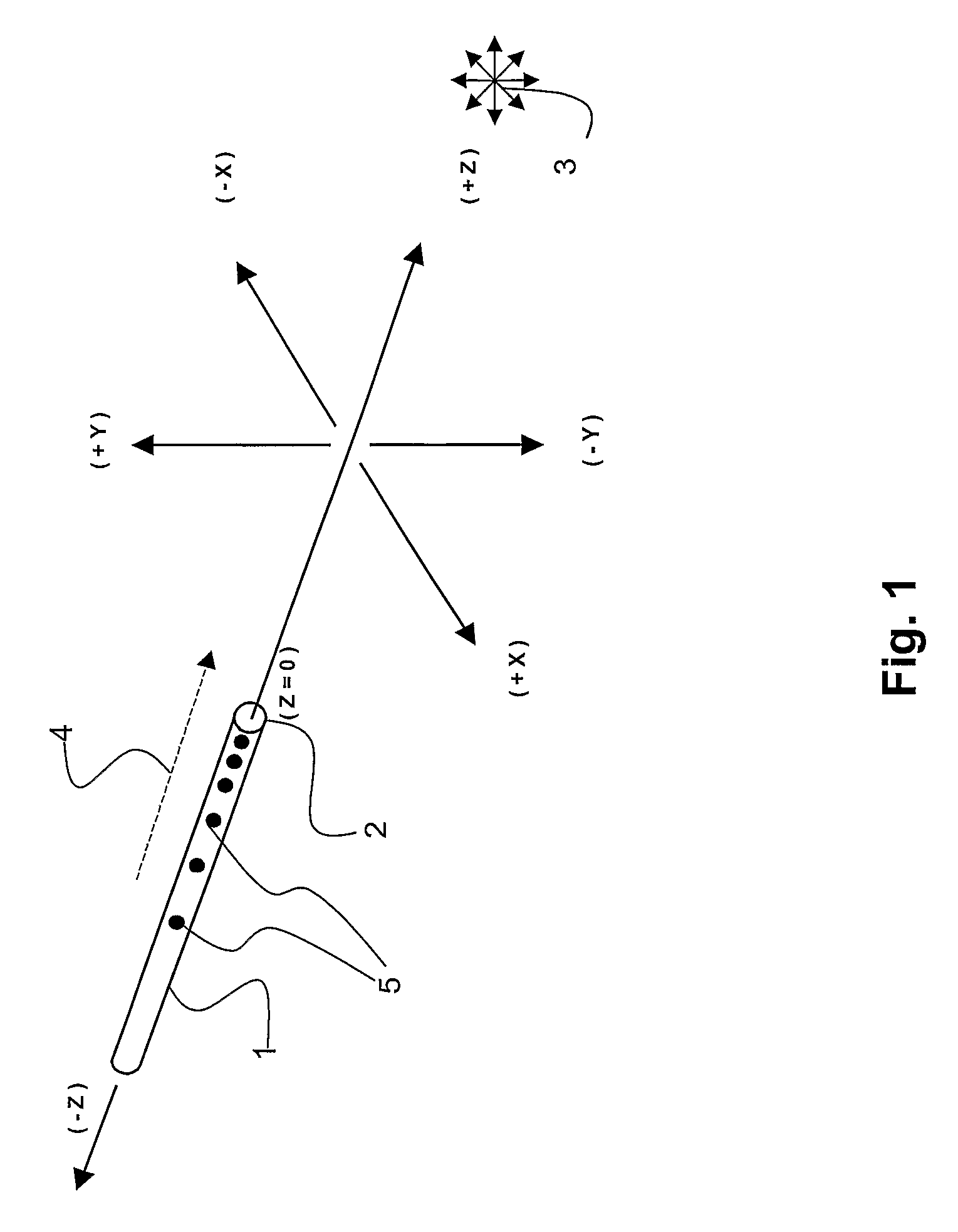
[0040]FIG. 1 shows a microphone array 1 having a reference end 2 and a sound source3 as well as a direction towards the sound source 4. An array of this type is often referred to as an “end-fire” microphone. The microphone array shown is a rectilinear element with individual microphones 5 disposed along the longitudinal axis, said microphone being disposed with the smallest spacing in the direction towards the sound source and a wider spacing away from the sound source. Basically, the length of the microphone array is at least as long as the wavelength of the lowest frequency, for which a high directivity is desired. The lowest frequency must be selected with care, as very low frequencies result in long microphone arrays of up to several meters in length. Moreover, at very low frequencies it is also doubtful, how much is achieved by a high directiv...


PUM


Abstract

Microphone array for achieving a substantially frequency-independent directivity using a plurality of microphones disposed along a rectilinear array. The rectilinear array is at least as long as the wavelength of the lowest frequency, where a useful directivity is desired. The rectilinear array has a first end and a second end. The microphones close to the first end are intended for the highest frequencies and the microphones close to the second end are intended for the lowest frequencies. The mutual spacing of the microphones is frequency-dependent. The signals from the individual microphones are band-pass filtered, the passbands and cut-off frequencies of the individual band-pass filters being adapted to the frequency band the individual microphones are intended for. The individual band-pass filters are adapted such that the amplitude of the summated signal after band-pass filtering is substantially the same when a sinus-shaped test signal is used, the amplitude of said test signal being constant and the frequency of said test signal varying within the frequency range where the microphone array is to have a substantially frequency-independent directivity.

Description

TECHNICAL FIELD[0001]The invention relates to a microphone array for achieving a substantially frequency-independent directivity using a plurality of microphones disposed along a rectilinear array.BACKGROUND ART[0002]A microphone array of this type can for example be used for recordings, where a frequency-independent directivity is desirable. Microphones are inter alia characterised by their sensitivity to different frequencies, but also by their sensitivity to the angle of incidence of the sound waves into the microphone. A microphone may, for example, have a spherical characteristic, where it receives sound waves substantially equally well from all angles, however, a microphone may also have a more or less conical directional characteristic. Thus, the microphone is highly sensitive to sound waves coming from a particular direction and less sensitive to sound waves coming from other directions. When microphones are used for the recording or transmission of, for example, music in a ...

Claims


Application Information

Patent Timeline
Patent Type & Authority Patents(United States)
IPC IPC(8): H04R3/00H04R1/26H04R1/40
CPCH04R1/406H04R3/005H04R2201/401H04R2201/403H04R2201/405H04R2430/23
Inventor SORENSEN, OLE MOLLER
Owner DPA MICROPHONES
Why Eureka
Try Eureka