Tilting Rack System

Active Publication Date: 2011-03-17
SKOGLUN JON E
View PDF13 Cites 7 Cited by
  • Summary
  • Abstract
  • Description
  • Claims
  • Application Information

AI Technical Summary

Problems solved by technology

However, the mechanism of Mistler requires an extensive retrofit to install, and its mechanism of operation is very complex and raises up high over the truck's cab, creating a potential hazard for impacts.

Method used


Image

  • Tilting Rack System
  • Tilting Rack System
  • Tilting Rack System

Examples


Embodiment Construction

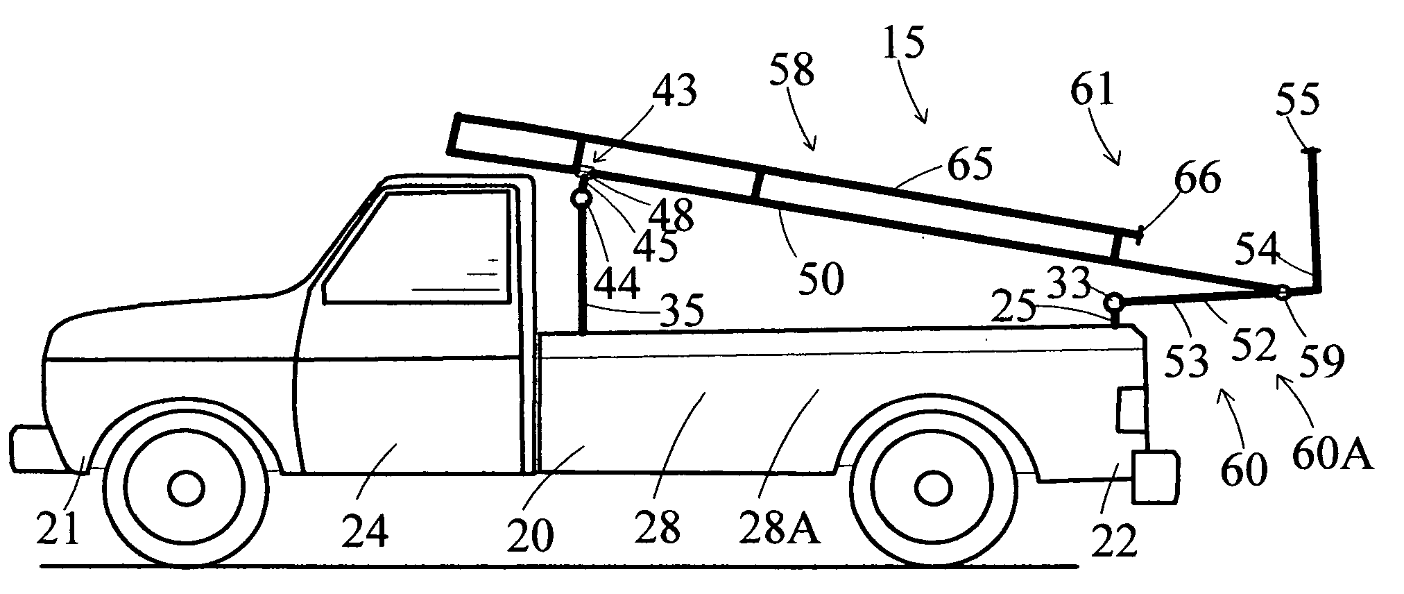
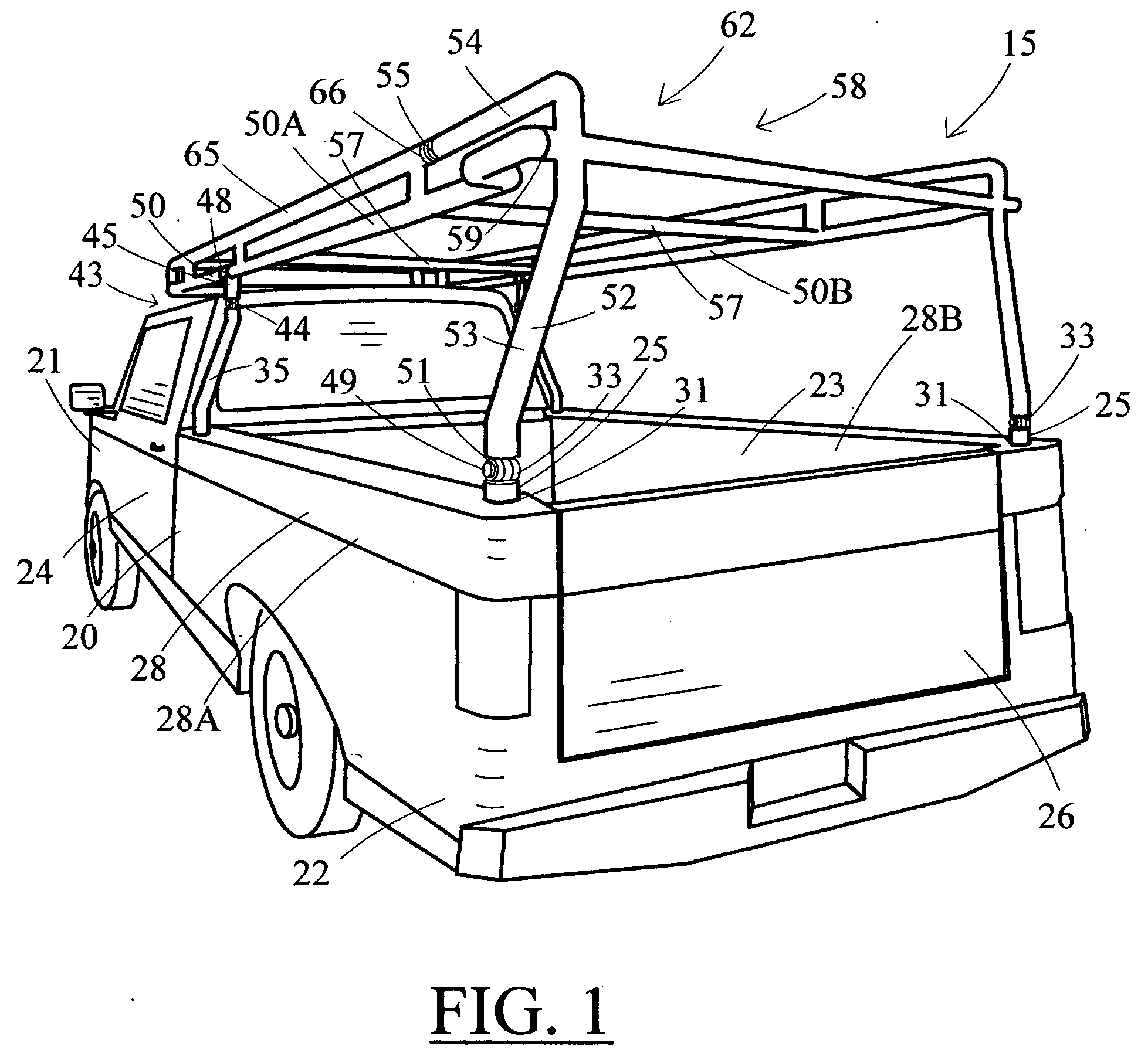
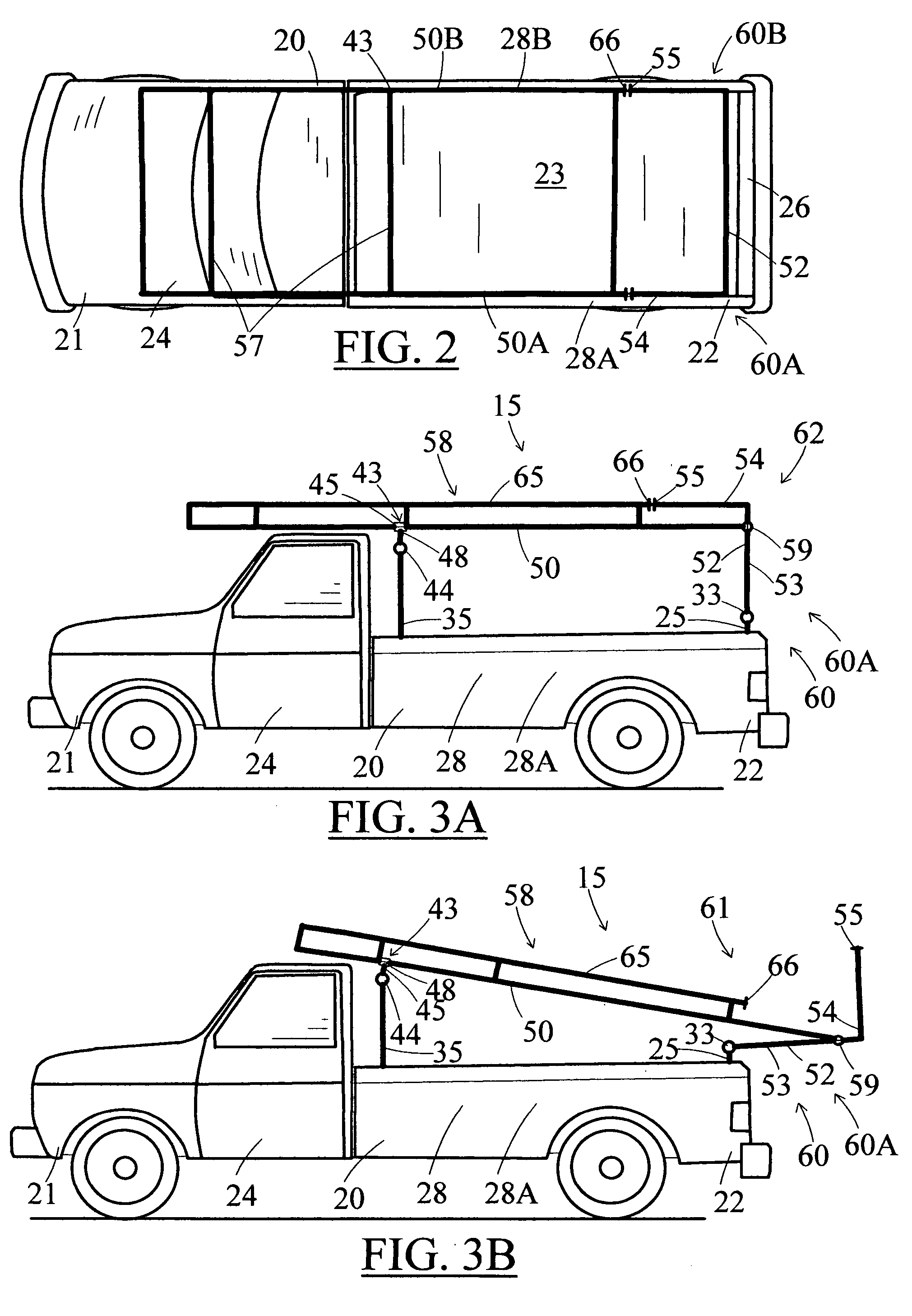
[0017]The present invention provides for a tilting rack system, specifically configured for a vehicle. FIGS. 1 through 7B show preferred embodiments of the tilting rack system 15, mounted on a vehicle 20, such as a conventional “pick-up” truck. In the conventional pick-up truck, a bed 23 abuts to a cab 24, and as also referenced throughout this written specification, the vehicle includes a forward end 21 and a rearward end 22, as illustrated in FIG. 1 through 4B.

[0018]The tilting rack system 15 includes a rearward support 25 mounted proximately to the rearward end 22 of the vehicle 20. For a pick-up truck, the rearward end is the end of the vehicle proximate to a tail gate 26. Preferably, the rearward support mounts upon a sidewall 28 of the truck. The sidewall extends upward from a bed-base 29, as shown in FIG. 2, and runs along the length of the bed 23, as shown in FIG. 1. In the typical truck, there are two sidewalls, a first sidewall 28A, opposite the width of the bed to a secon...


PUM


Abstract

An apparatus for tilt-able rack system especially suited for a vehicle, such as a pick-up truck. The tilting rack system includes a stationary upright support frame, and a hinged upright support, with the hinged upright mounted to the vehicle rearward of the stationary upright. A slide-able and tilt-able pair of rails mount to the support frame at the hinged and stationary uprights. As the hinged uprights lever rearward and downward, by action of a hinge at the base of each upright, the rails can slide and tilt upon a sliding hinge at the top of each stationary upright. The rearward, hinged uprights may be actuated by hydraulics, manual cranks, cables, or any other such mechanisms. The entire rail and associated frame can tilt down to the rear of the vehicle, allowing the easy placement of long items on the frame, such as ladders, pipes, boats, boards, and panels.

Description

TECHNICAL FIELD[0001]The invention relates to a tilting rack system for a vehicle, which is especially suited for use with a pick-up truck, and more specifically a tilting rack system that includes a levered end-bar that raises or lowers an overhead rack, allowing the rack to tilt rearward as it slides for easy access. The tilting rack system of the present invention is useful for the loading or unloading for pipes, ladders, lumber, or other such items or materials on the rack.BACKGROUND OF THE INVENTION[0002]Several prior truck rack systems include overhead actuation features that ease the loading and unloading of long or bulky items over the top of the truck's bed, and then over the cab of the truck. U.S. Pat. No. 6,676,220 to Mistler, for instance, includes a ‘dump-truck’ type of mechanism to tilt the rack of the pick-up truck. However, the mechanism of Mistler requires an extensive retrofit to install, and its mechanism of operation is very complex and raises up high over the tr...

Claims


Application Information

Patent Timeline
IPC IPC(8): B62D33/08
CPCB62D33/08B62D33/02
Inventor SKOGLUN, JON E.
Owner SKOGLUN JON E
Why Eureka
Try Eureka