
Press-in element, component assembly consisting of a press-in element and a sheet metal part and also methods for the manufacture and attachment of a self-piercing press-in nut

a self-piercing, press-in element technology, applied in the direction of nuts, fastening means, applications, etc., can solve the problems of unusable use, unusable weld elements with diverse sheet metal parts, unusable contamination of sheet metal parts, etc., to achieve rational use and manufacture at favorable prices

Active Publication Date: 2011-03-24
PROFIL VERBINDUNGSTECHN
View PDF12 Cites 3 Cited by
  • Summary
  • Abstract
  • Description
  • Claims
  • Application Information

AI Technical Summary

Benefits of technology

[0009]The object of the present invention is to propose a self-piercing press-in element and a component assembly consisting of a press-in element and a sheet metal part as well as a method for the manufacture of such a press-in nut and such a component assembly which can be manufactured at favorable price or carried out even with small numbers of parts and can be rationally used. In order to satisfy this object a self-piercing press-in element is provided in accordance with the first aspect of the present invention, in particular a nut element for attachment to a sheet metal part, wherein the press-in element has a flange part of a larger diameter and a shaft part of a smaller diameter, with the shaft part extending away from the flange part and having a circular piercing edge at its end face remote from the flange part, wherein the side of the flange part facing the shaft part forms a sheet metal contact surface in ring shape and features providing security against rotation are provided at the shaft part which extend approximately from the level of the sheet metal contact surface over a part of the length of the shaft part along the latter.
[0010]Through this design a sharper transition can be provided between the ring-like sheet metal contact surface and the shaft part, whereby the element can be introduced in self-piercing manner into the sheet metal part and it is ensured that the flange part closely contacts the sheet metal part and that no disturbing radii or features are provided in the transition region which could hinder a firm seat of the ring-like contact surface at the sheet metal part. In this way the element can be firmly pressed into engagement with the sheet metal part without a spacing resulting between the sheet metal contact surface and the side of the sheet metal part facing it.
[0011]In this way settlement effects can be avoided reliably in operation whereby the bolt screwed into the hollow press-in element always retains the preset tension and the bolted connection does not become prematurely loose or fail, for example due to settlement effects. In the claimed design one press-in element can be used with various sheet metal thicknesses.
[0013]It is particularly favorable with a design of this kind when the said ribs or noses arise during manufacture of the features providing security against rotation such that a tool having corresponding grooves is placed over the shaft part of the press-in element and material is displaced from the region between the ribs and the noses partly into the ribs and noses and partly axially shifted up to and into the ring-like recess in the flange part where, so to say, the excess material can be hidden and indeed without preventing a sharp transition from the ring-like sheet metal contact surface into the outer side of the shaft part.
[0022]The features providing security against rotation are preferably formed by noses or ribs which extend in the axial direction of the shaft part along the shaft part. Recesses, which correspond to the noses or ribs providing security against rotation are then present in the sheet metal part. The press-in element is preferably a fastener element having a hollow shaft part with a central thread which extends through the flange part and the shaft part. Through the pronounced radial thickness of the shaft part it need not be feared that the shaft part will be compressed during the attachment to the sheet metal part so that the fastener element does not become excessively tall when providing an adequate length of the thread and thus is not excessively heavy.
[0023]A method for the manufacture of a self-piercing press-in nut having a flange part of larger diameter and a shaft part of smaller diameter extending away from the flange part, wherein the shaft part has a circular piercing edge at its end remote from the flange part is characterized in that one takes a blank having a cross-sectional shape corresponding to that of the flange part and the shaft part, with the shaft part having a smaller diameter in the region of the free end in the blank than in the region adjacent to the flange part, in that an axial recess is formed in the flange part adjacent to the shaft part and in that material in the region of the shaft part having the larger diameter is scraped away at a plurality of positions spaced apart around the periphery by means of a scraper with the scraped away material being introduced into the axial recess of the flange part and with noses or ribs remaining in the region between the scraped away regions which form features of the element providing security against rotation.

Problems solved by technology

The press-in element is thus locked to the sheet metal part in this way so that it is securely fastened to the sheet metal part and cannot be straightforwardly pressed axially out of the sheet metal part or rotated relative to the sheet metal part with the usual torques which arise on attaching a bolt or a nut.
The welding on of elements can, on the one hand, only be poorely integrated into the process of manufacture of individual sheet metal parts by mechanical deformation and leads also to an undesired contamination of the sheet metal part.
Furthermore weld elements cannot be used with diverse sheet metal parts such as, for example, sheet metal parts which are pre-painted or which consist of two sheet metal layers, optionally with a plastic membrane disposed between them.
They can also not be used when the sheet metal part is a high strength sheet metal part since the heat which arises during the welding leads to an unacceptable reduction of the characteristics of the sheet metal in the region of the weld position.
A press-in element of this kind certainly has its justification but is however relatively complicated in its manufacture.
Furthermore, the design in the region of the ring surface and directly below the ring surface at the neck part can under some circumstances lead to greater difficulties during the attachment of the sheet metal part as the desired form-fitted locking which aimed at with the sheet metal part cannot be ensured under some circumstances to the desired level.
An element of this kind is entirely able to satisfy its task is however relatively complicated and is also not well suited to be used in a self-piercing manner in really thick sheet metal parts in the range from 4 mm thickness and above.
Furthermore, many fewer trucks are manufactured in comparison to motorcars.

Method used


Image

  • Press-in element, component assembly consisting of a press-in element and a sheet metal part and also methods for the manufacture and attachment of a self-piercing press-in nut
  • Press-in element, component assembly consisting of a press-in element and a sheet metal part and also methods for the manufacture and attachment of a self-piercing press-in nut
  • Press-in element, component assembly consisting of a press-in element and a sheet metal part and also methods for the manufacture and attachment of a self-piercing press-in nut

Examples


Embodiment Construction

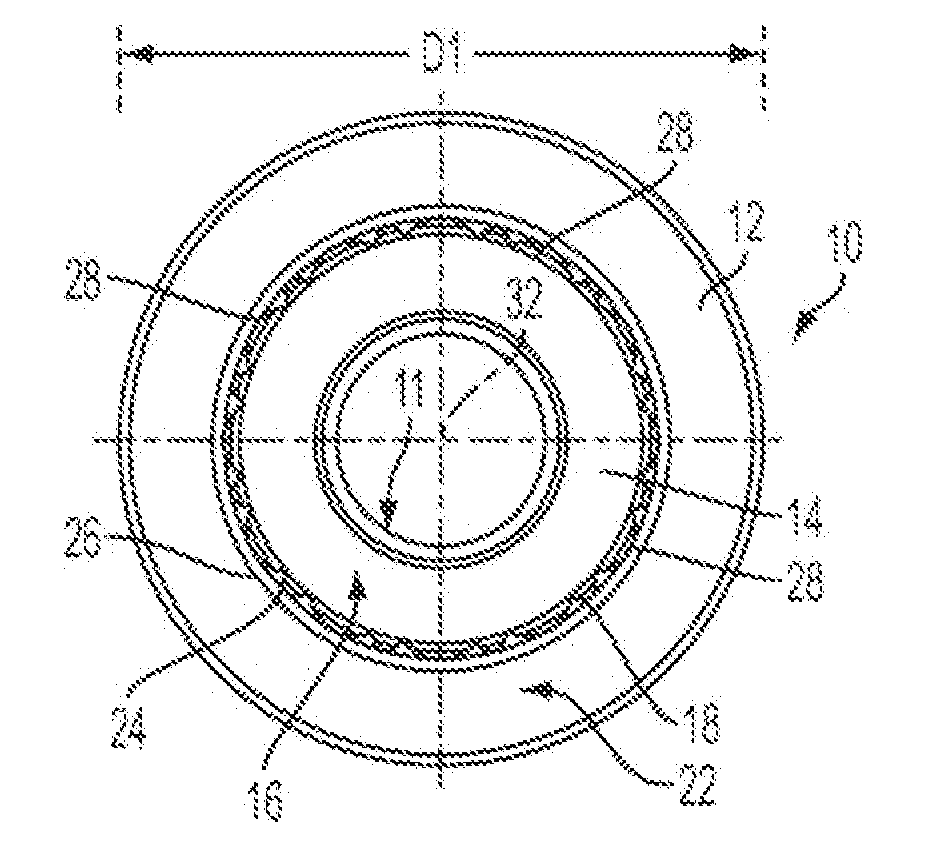
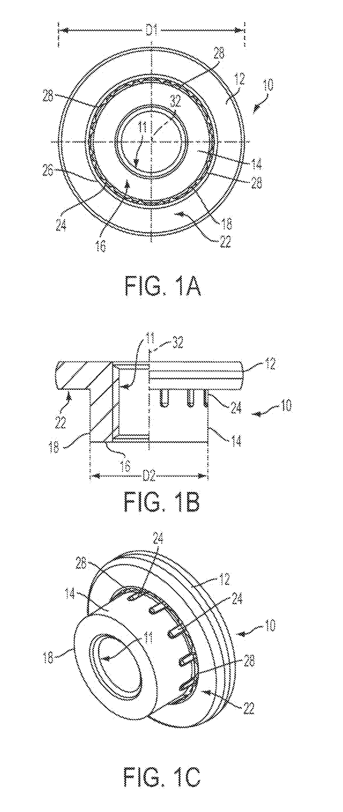
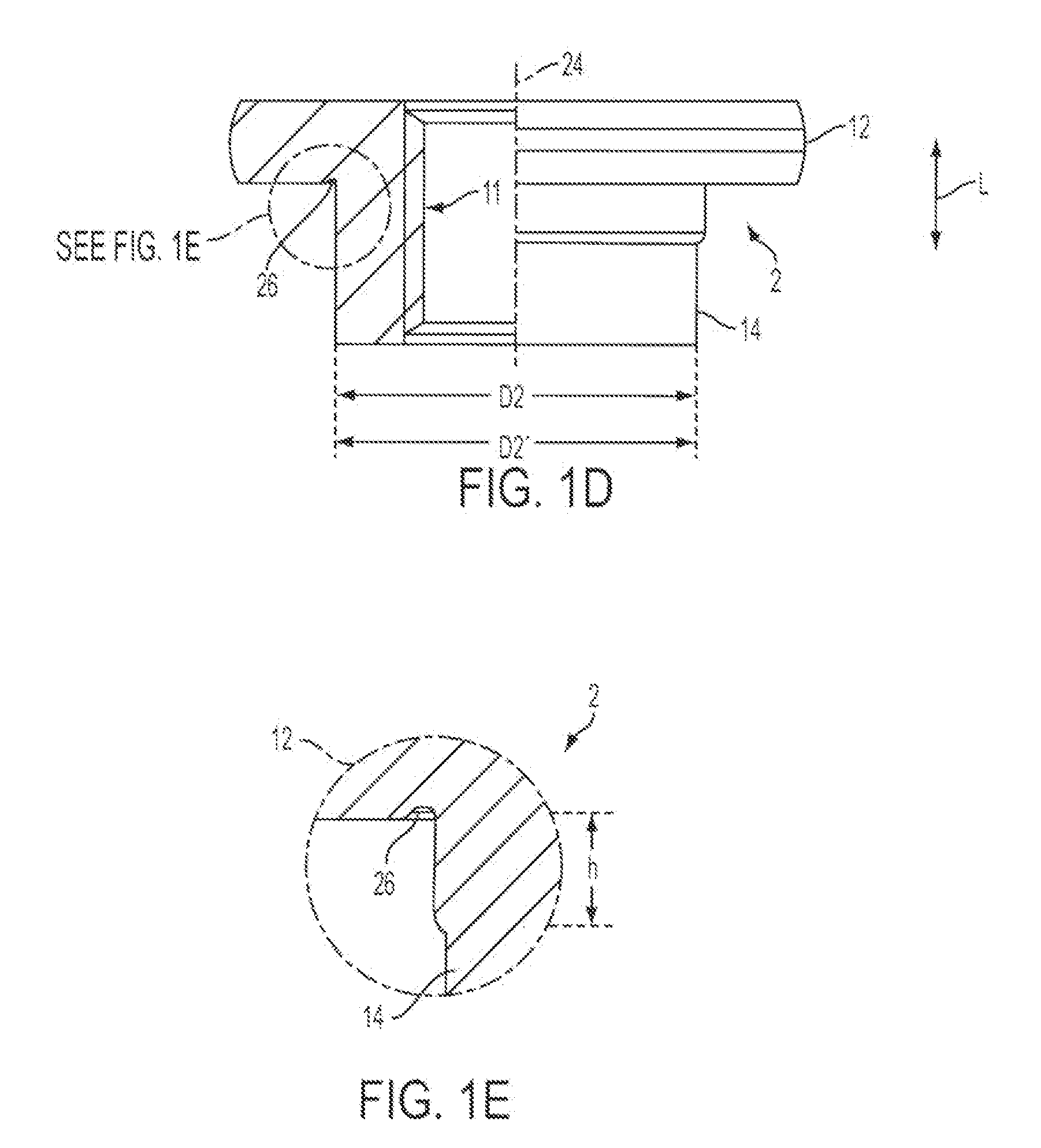
[0038]The FIGS. 1A to 1C show a self-piercing hollow press-in element 10 in the form of a nut element in attachment to a sheet metal part. The press-in element 10 has a flange part 12 of a larger diameter D1 and a shaft part 14 of smaller diameter D2, with the shaft part 14 extending away from the flange part 12 and having a circular piercing edge 18 at its end 16 remote from the flange part 12. The side of the flange part 12 adjacent the shaft part 14 forms a sheet metal contact surface 22 of ring-shape and features 24 providing security against rotation are provided at the shaft part. These features extend from approximately the level of the sheet metal contact surface 22 over a part of the length of the shaft part 14, for example over about 40% of the length of the shaft part 14 along the latter.

[0039]A ring-shaped recess 26 is provided in the flange part 12 radially within the sheet metal contact surface 22 of ring shape. The ring recess 26 can also be recognized in the blank in...


PUM

PropertyMeasurementUnit
diameter D2aaaaaaaaaa

Abstract

A self-piercing hollow press-in element, in particular a nut element for attachment to a sheet metal part, wherein the press-in element has a flange part of a larger diameter and a shaft part of a smaller diameter. The shaft part extends away from the flange part and has a circular piercing edge at its end face remote from the flange part. The side of the flange part facing the shaft part forms a sheet metal contact surface in ring shape and features providing security against rotation are provided at the shaft part which extend approximately from the level of the sheet metal contact surface over a part of the length of the shaft part along the latter. A ring-like recess is provided radially within the ring-shaped sheet metal contact surface in the flange part and excess material for the shaft part which arises during manufacture of the ribs providing security against rotation is located within the ring recess. Further designs of the press-in element and also of a component assembly and methods for the manufacture of the press-in element and of the component assembly are described.

Description

CROSS-REFERENCE TO RELATED APPLICATIONS[0001]This application claims priority of German Patent Application No. 10 2009 042 336.2, filed Sep. 21, 2009, the disclosure of which is expressly incorporated by reference herein in its entirety.FIELD OF THE INVENTION[0002]The present invention relates to a self-piercing hollow press-in element, to a component assembly consisting of a press-in element and a sheet metal part and also to a method of manufacturing a self-piercing press-in nut and also to a method for the attachment of a self-piercing press-in nut.BACKGROUND OF THE INVENTION[0003]In the manufacture of motorcar bodies and parts it is absolutely usual to operate with fastener elements which are present in the form of rivet elements, piercing elements or press-in elements.[0004]With a rivet element the element is inserted into a pre-pierced sheet metal part and riveted to the sheet metal part by beading over the rivet section of the fastener element. The fastener element itself has...

Claims


Application Information

Patent Timeline
Patent Type & Authority Applications(United States)
IPC IPC(8): B21D31/00B21D53/24F16B37/00
CPCF16B37/068
Inventor BABEJ, JIRI
Owner PROFIL VERBINDUNGSTECHN
Learn More