Surface-tolerant RFID transponder device

Active Publication Date: 2011-03-24
NXP BV
View PDF5 Cites 30 Cited by
  • Summary
  • Abstract
  • Description
  • Claims
  • Application Information

AI Technical Summary

Benefits of technology

The carrier assembly is configured for receiving an RFID transponder chip. In operational use the RFID transponder chip is mounted to the carrier assembly such that its contacts are connected to the antenna contacts which completes the respective RF circuit. The antenna is required for receiving an RF signal from an RFID-reader. Besides information contained in the signal the energy contained in this signal is used for powering the transponder chip such that it may transmit information back to the RFID-reader via the same antenna. The carrier assembly may have the form of a sticker (based upon a paper or plastic substrate) or a flexible card. In operational use the carrier assembly is typically provided on a surface of a product or on or in a package. The magnetic layer ensures that the antenna layer may collect energy even if the RFID transponder is directly provided on a metal surface. It allows a part of the magnetic flux to pass through the magnetic layer and not contribute to Eddy currents. As a result some magnetic field remains to power the transponder and allow operation. Despite the presence of the magnetic layer detuning of the resonance frequency of the antenna occurs, i.e. the total inductance (self-inductance plus mutual inductance) of the antenna is affected by the presence of the material (having magnetic properties) on which the RFID transponder is provided. Expressed differently, a different material will result in a different total inductance and thus in a different detuning of the resonance frequency. It must be noted that the operating carrier frequency is generally standardized, it is 13.56 MHz in the ISO/IEC14443 standard, for example. For best energy transfer, the resonance frequency should b

Problems solved by technology

A typical transponder card attached to a metal plate will not operate properly, because the magnetic flux passing through the antenna coil will produce eddy currents in the metal, and these will produce an opposite H-field, which practically cancels out completely the Reade

Method used


Image

  • Surface-tolerant RFID transponder device
  • Surface-tolerant RFID transponder device
  • Surface-tolerant RFID transponder device

Examples


first embodiment

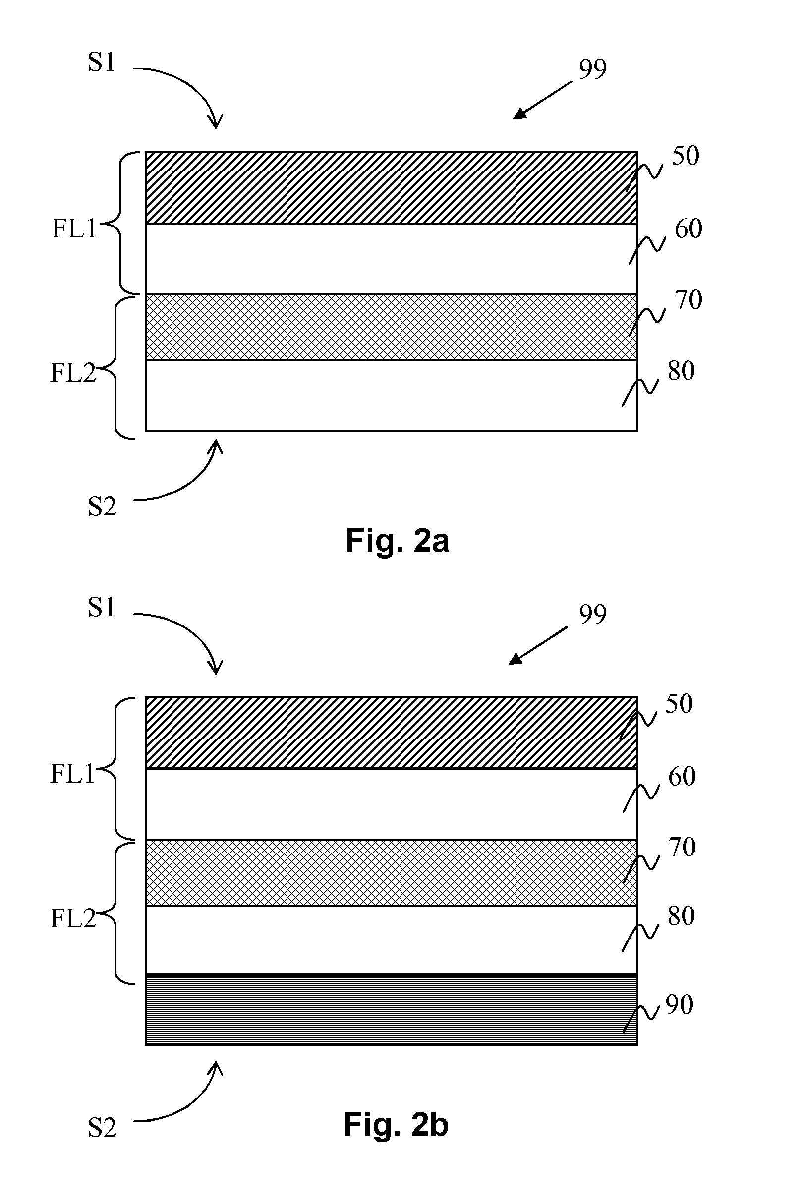
FIG. 2b shows a schematic cross-sectional view of part of an RFID carrier assembly for an RFID chip according to the invention.

This figure will be discussed in as far as it differs from FIG. 2a. At the attachment side S2 of the RFID carrier assembly 99 there is provided an electrically conductive shielding layer 90. In this example the shielding layer comprises copper (may be referred to as copper backplane). A typical thickness is 18 μm or 35 μm in case of copper. A minimum thickness is in the order of 2 μm, which may be producible with galvano-antenna technology. As already mentioned the purpose of the shielding layer 90 is to make the detuning effect of the RFID transponder less dependent from the environment, i.e. to make the RFID transponder suitable for being used on different surfaces having different materials, even though the RFID transponder has only been optimized for once specific situation. The first substrate layer 60 and the second substrate layer 70 may comprise poly...

second embodiment

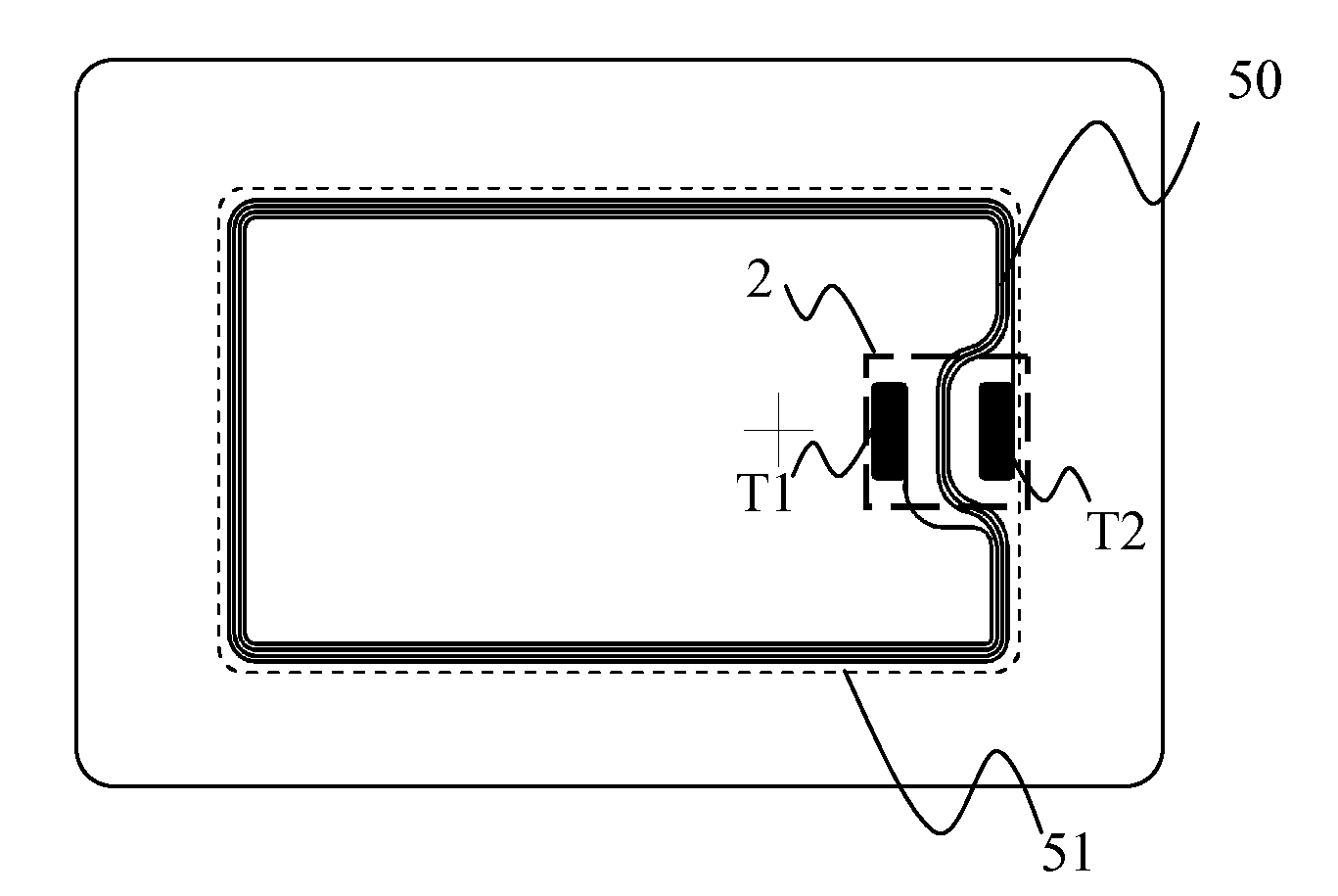
FIGS. 4a to 4c illustrate schematic transparent layout views of an RFID transponder device according to the invention. FIG. 4a shows a transparent layout view of the RFID transponder device. It shows the antenna 50 which comprises a number of loops and ends up into a first antenna terminal T1 and a second antenna terminal T2. The antenna terminals T1, T2 are configured for being connected with pins of an RFID transponder chip 2. FIG. 4a also shows an outer contour 51 of the antenna 50. FIG. 4b shows a transparent layout view of the RFID transponder device comprising the magnetic layer 70. The magnetic layer 70 has an outer contour 71 which fully encloses the outer contour 51 of the antenna. The advantage of this embodiment is that the magnetic flux is better confined within the magnetic layer 70 and guided in between the antenna layer and the object onto which the transponder is provided. The more the outer contour 71 of the magnetic layer 70 extends beyond the contour 51 of the ant...


PUM


Abstract

A carrier assembly for receiving an RFID transponder chip has an attachment side for being attached to a consumer device and an operation side for receiving an RF signal in operational use of the RFID transponder chip.

Description

This application claims the priority of European patent application no. 09170539.2, filed on Sep. 17, 2009, the contents of which are incorporated by reference herein.BACKGROUND OF THE INVENTIONToday, a huge amount of personal cards is in practical use, with an increasing focus on applications requiring higher security. RFID technology was implemented as a comfortable interface for the user and world-wide standardized about one decade ago in the ISO / IEC14443 Proximity Standard. This standard, as well as all other standards in the field of RFID are considered to be well-known to the person skilled in the art. RFID technology enabled electronic passports, contactless credit cards (E-banking), access control or public transport ticketing as successful solutions being part of our daily life. The typical format of such cards is ID-1, specified in the ISO / IEC7810 standard.A new trend is visible wherein RFID technology is being used for payment applications. In such applications contactles...

Claims


Application Information

Patent Timeline
IPC IPC(8): G06K19/077H01Q1/00
CPCG06K19/07749G06K19/07771H01Q19/10H01Q7/00H01Q1/2225
Inventor GEBHART, MICHAEL
Owner NXP BV
Why Eureka
Try Eureka