Connector block for shock tubes and method of securing a detonator therein

Inactive Publication Date: 2005-01-27
ORICA EXPLOSIVES TECH PTY LTD
View PDF12 Cites 6 Cited by
  • Summary
  • Abstract
  • Description
  • Claims
  • Application Information

AI Technical Summary

Benefits of technology

[0029] The connector block of the present invention may further comprise a membrane having positioning membrane located within the bore adjacent to the signal transmission end, for accurately positioning the percussion-actuation end of the detonator in signal transfer relationship with the shock tubes located in the slot. In this manner, the present invention allows a detonator to be secured within a connector block in a position that is optimal for energy transfer from the percussion-actuation end of the detonator to the shock tubes. Importantly, any incorrect positioning of the percussion-actuation end of the detonator, resulting from any divergence in the dimensions of the conn

Problems solved by technology

Shock tubes that fail to initiate result in unexploded charges at the blast site, with inevitable safety concerns.
If any gap is present between the detonator end and the shock tubes, the transfer of actuation energy may be less efficient, thus resulting in an increased failure rate of shock tube initiation.
However, excess pressure from the percussion-actuation end of the detonator upon the shock tubes can result in the distortion of the shock tubes, and consequently the reduction of shock tube internal volume within the connector block.
This in turn reduces the capacity of the shock tubes for efficient initiation, since their capacity for rapid compression is also reduced.
However, slight differences between connector blocks are unavoidable due to tolerances in the plastic resulting from both the manufacturing process, and from the

Method used


Image

  • Connector block for shock tubes and method of securing a detonator therein
  • Connector block for shock tubes and method of securing a detonator therein
  • Connector block for shock tubes and method of securing a detonator therein

Examples


Embodiment Construction

[0036] Preferred embodiments of the present invention are described in the following with reference to the accompanying drawings.

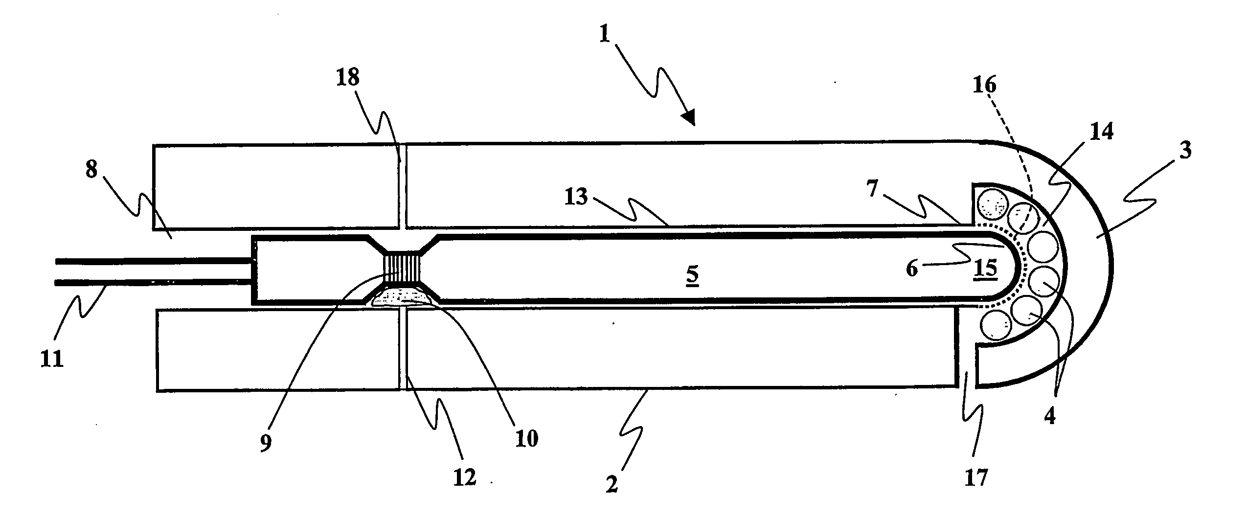
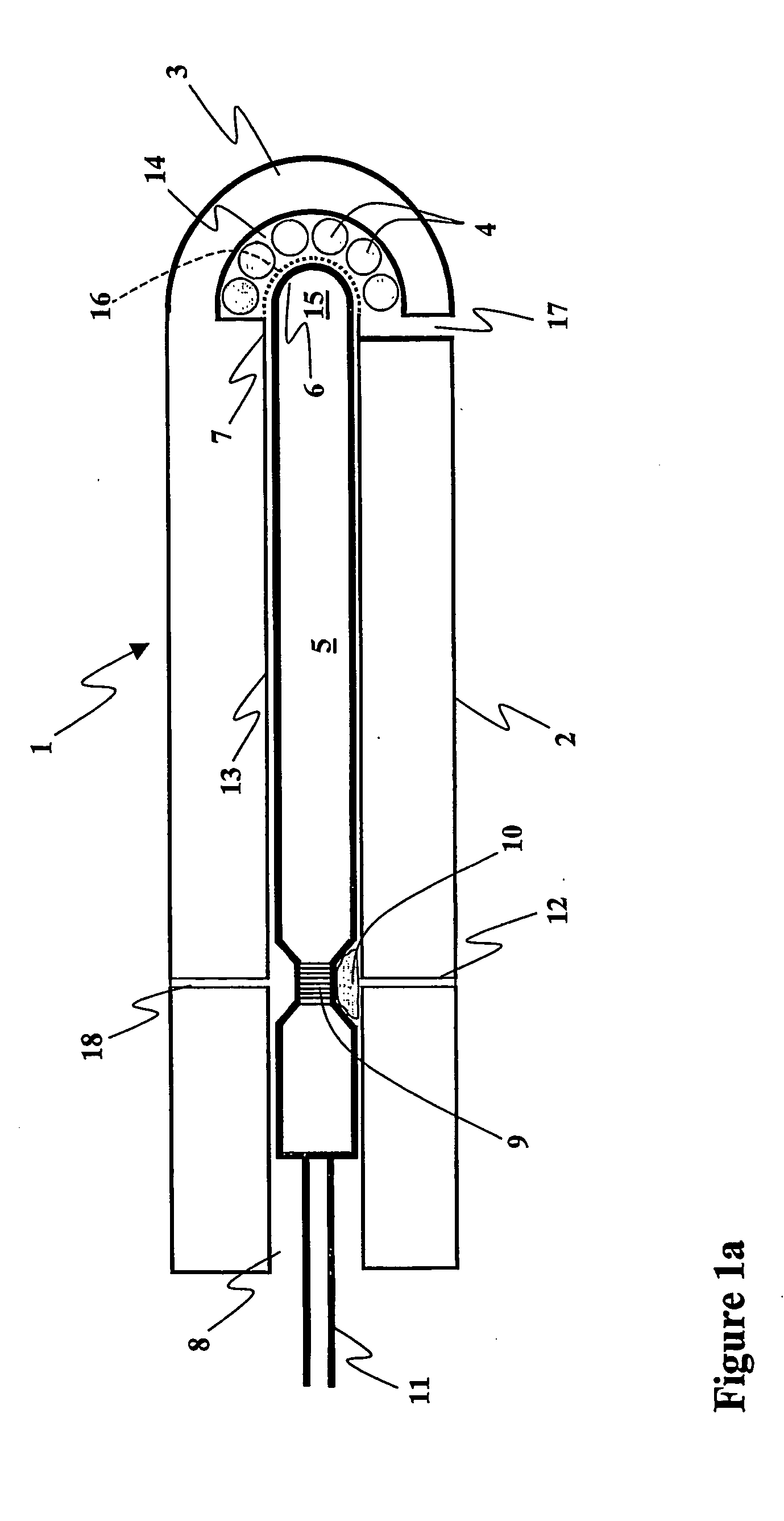
[0037]FIG. 1a illustrates a first preferred embodiment of the present invention, wherein a body of material in the form of a settable locking material is injected into the connector block to secure a detonator positioned therein. The connector block 1 is shown in longitudinal cross-section. The connector block comprises a housing 2, preferably made of a plastics material, with a cylindrical bore 13 running longitudinally through the housing. The bore 13 has an open end 8 and a signal transmission end 7.

[0038] While the bore 13 of all of the illustrated embodiments is formed as a cylindrical through hole, it will be appreciated by persons skilled in the art that the bore may alternatively be an open-sided slot or trough. However, a bore having a cross-section that is identical to, or closely approximates, that of a detonator to be used in the device, will...


PUM


Abstract

A method of producing an assembly of a connector block (1, 21, 40) and a detonator (5, 25,41) suitable for retaining at least one shock tube (4, 24) adjacent to a percussion-actuation end (15, 26) of the detonator, and to an assembly thus produced and a connector block therefor. The method comprising inserting a detonator into a connector block having a housing (2, 22, 40) provided with a bore (13, 31, 44), positioning the detonator in the bore of the housing so that the percussion-actuation end of the detonator is positioned adjacent to a slot (14, 35) for receiving the shock tubes; and fixing the detonator in the housing. The detonator is fixed in the housing by causing a body of material (10) to flow plastically into the recess in the detonator and to harden therein to form a locking element fixed to the housing, thereby preventing accidental movement of the detonator within the connector block.

Description

FIELD OF THE INVENTION [0001] The present invention relates to connector blocks for the initiation of shock tubes. Connector blocks provide a means for transferring the actuation energy of a detonator to one or more shock tubes (also known as signal transmission lines) for use in the explosives industry. More particularly, the present invention relates to means and methods for securing a detonator within a connector block of this kind, and to assemblies of connector blocks with detonators pre-positioned therein. BACKGROUND OF THE INVENTION [0002] In commercial blasting operations, a series of explosions is frequently triggered in an exact order with precise timing. For this purpose, blasting systems have been developed that employ shock tubes also known as signal transmission lines that transfer a blast initiation signal to a series of explosive charges. To facilitate this, a signal from a single shock tube can be transferred to multiple shock tubes in a blasting system via the use ...

Claims


Application Information

Patent Timeline
IPC IPC(8): C06C5/06F42D1/04
CPCF42D1/043C06C5/06
Inventor HUSK, PETER THOMASGOURLAY, ROSS IAN
Owner ORICA EXPLOSIVES TECH PTY LTD
Why Eureka
Try Eureka