[0002]
Photovoltaic power generation systems are currently constructed by installing a foundation system (typically a series of posts), a module structural support frame (typically brackets, tables or rails, and clips), and then mounting PV modules, also known as solar panels, to the support frame. The PV modules are then grouped electrically together into PV strings, which are fed to an electric harness. The harness conveys
electric power generated by the PV modules to an aggregation point and onward to electrical inverters.
[0002]Photovoltaic power generation systems are currently constructed by installing a foundation system (typically a series of posts), a module structural support frame (typically brackets, tables or rails, and clips), and then mounting PV modules, also known as solar panels, to the support frame. The PV modules are then grouped electrically together into PV strings, which are fed to an electric harness. The harness conveys electric power generated by the PV modules to an aggregation point and onward to electrical inverters.
[0002]Photovoltaic power generation systems are currently constructed by installing a foundation system (typically a series of posts), a module structural support frame (typically brackets, tables or rails, and clips), and then mounting PV modules, also known as solar panels, to the support frame. The PV modules are then grouped electrically together into PV strings, which are fed to an electric harness. The harness conveys electric power generated by the PV modules to an aggregation point and onward to electrical inverters.
[0003]Conventional methods and systems of mounting a PV module to a rail or other structural support frame typically uses four module edge clips with rubber inserts that must be screwed into the rail in the field in parallel with installing the module on the rail. These methods and systems require screwing the clip halfway down, setting the upper and lower PV modules associated with the clip in place, and final tightening of the clip screw to secure the module to the rail. This process of handling the clips, half way setting the clip, setting the PV modules and finally tightening the clips is slow and labor intensive.
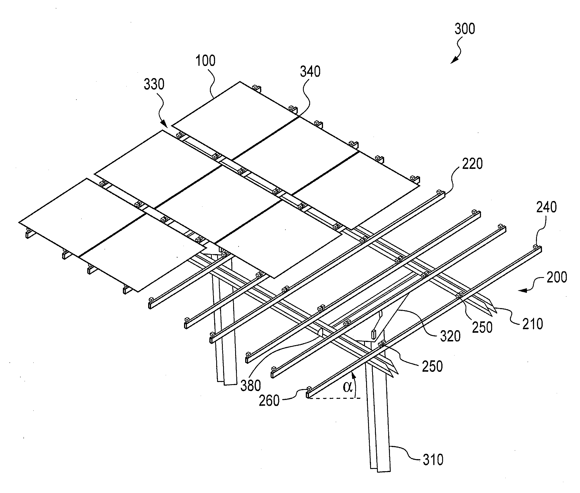
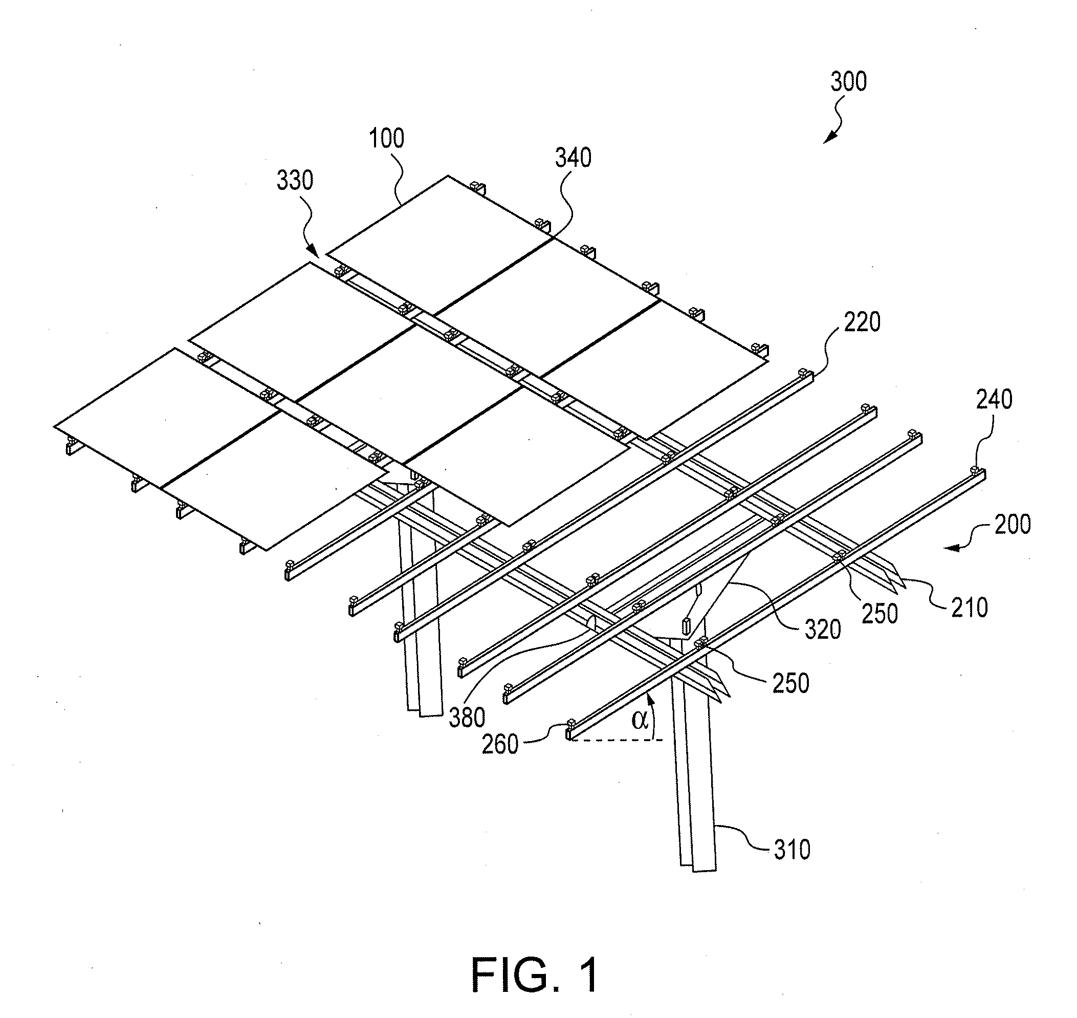
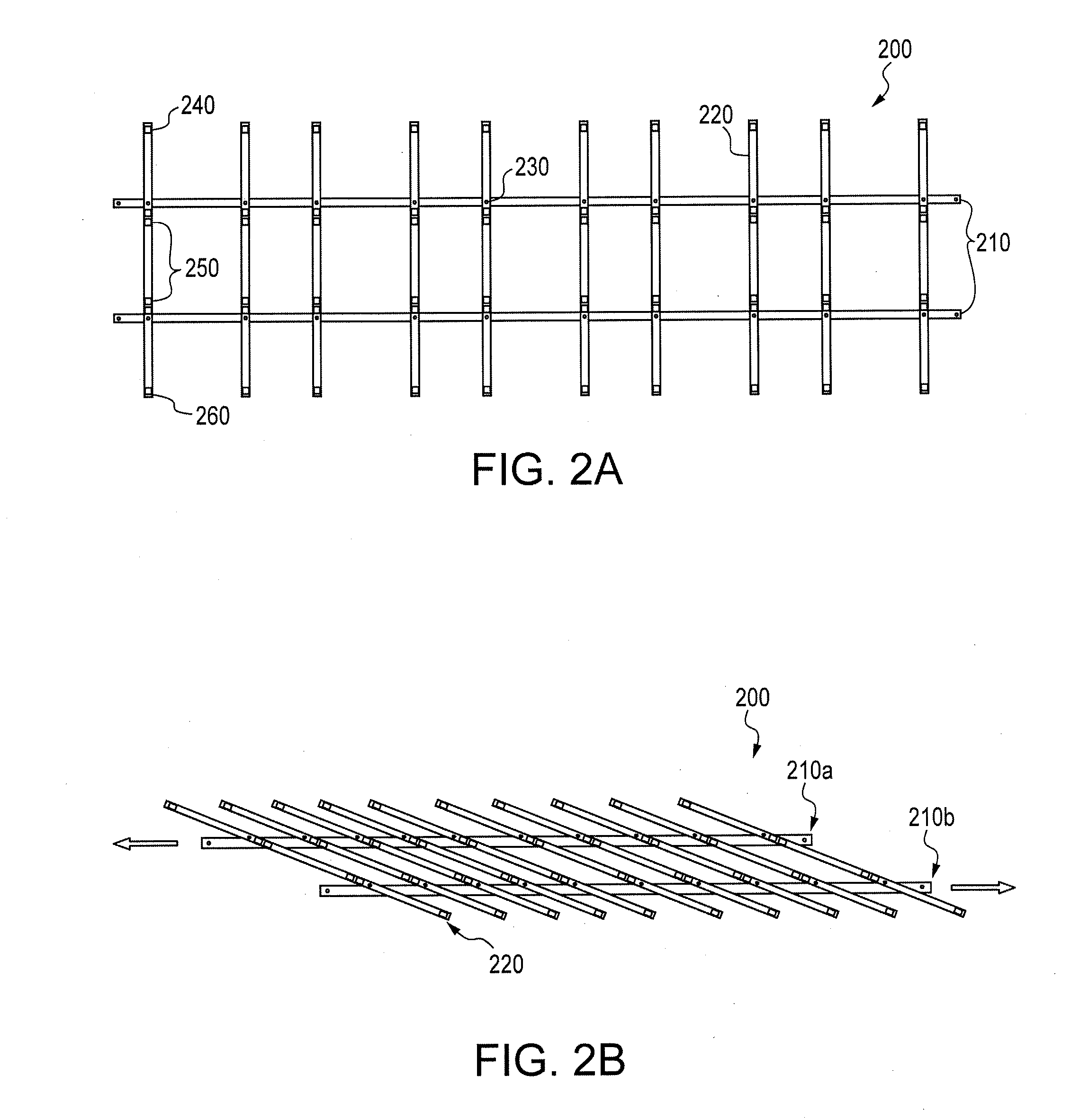
[0025]Described herein is a mounting system and slider clips that support simplified installation of photovoltaic (PV) structures. The mounting system comprises a support structure which can be mounted to support columns via an optional tilt table. The support structure comprises a plurality of parallel spaced beams and a plurality of parallel spaced rails that are mounted perpendicular to the beams. Disclosed embodiments describe a collapsible support structure in which the rails are pivotally mounted to the beams. Rails are preassembled with slider clips for holding edge portions of the photovoltaic structures and allowing for easy slide in
insertion of the photovoltaic structures into the slider clips. Rails can also be integrally formed with slider clips. The mounting system maximizes the use of prefabricated and preassembled components and reduces the on-site field labor costs associated with installing the PV structures. Described herein are also methods of installing one or more photovoltaic structures using the mounting system and methods for manufacturing slider clips and a photovoltaic structure mounting system.

