Position detecting device

a technology of position detection and capacitance system, which is applied in the direction of resistance/reactance/impedence, instruments, code conversion, etc., can solve the problems of lowering the accuracy of position detection by the capacitance system, and achieve the effect of preventing the lowering of the accuracy of position detection

Active Publication Date: 2011-03-24
WACOM CO LTD
View PDF9 Cites 19 Cited by
  • Summary
  • Abstract
  • Description
  • Claims
  • Application Information

AI Technical Summary

Benefits of technology

[0011]It is desirable that the above-described conductor has a shape that reduces the occurrence of an eddy current on the surface, preferably a shape having a slit extending from an outer edge of the conductor toward the inside of the conductor. This feature can prevent the o

Problems solved by technology

If wiring (wires) led out from this detection area is arranged in an area adjacent to the detection area, even the capacitance of the wiring

Method used


Image

  • Position detecting device
  • Position detecting device
  • Position detecting device

Examples


Embodiment Construction

[0020]A position detecting device according to one embodiment of the present invention will be described below with reference to the drawings.

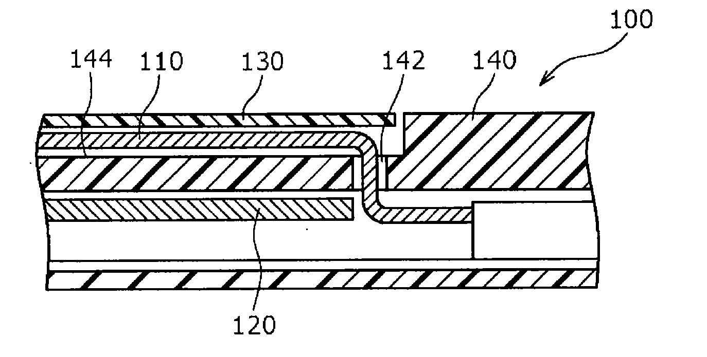
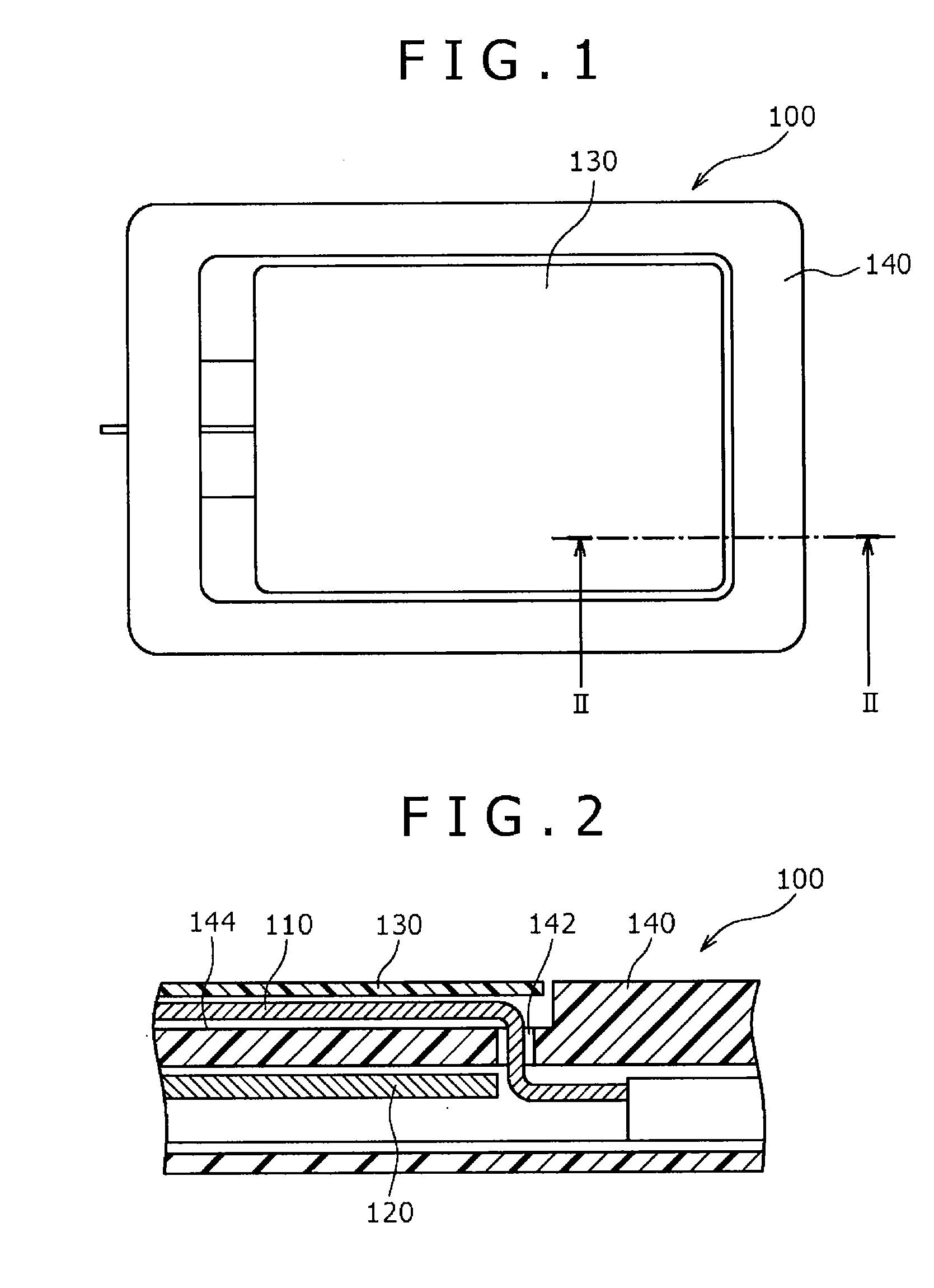
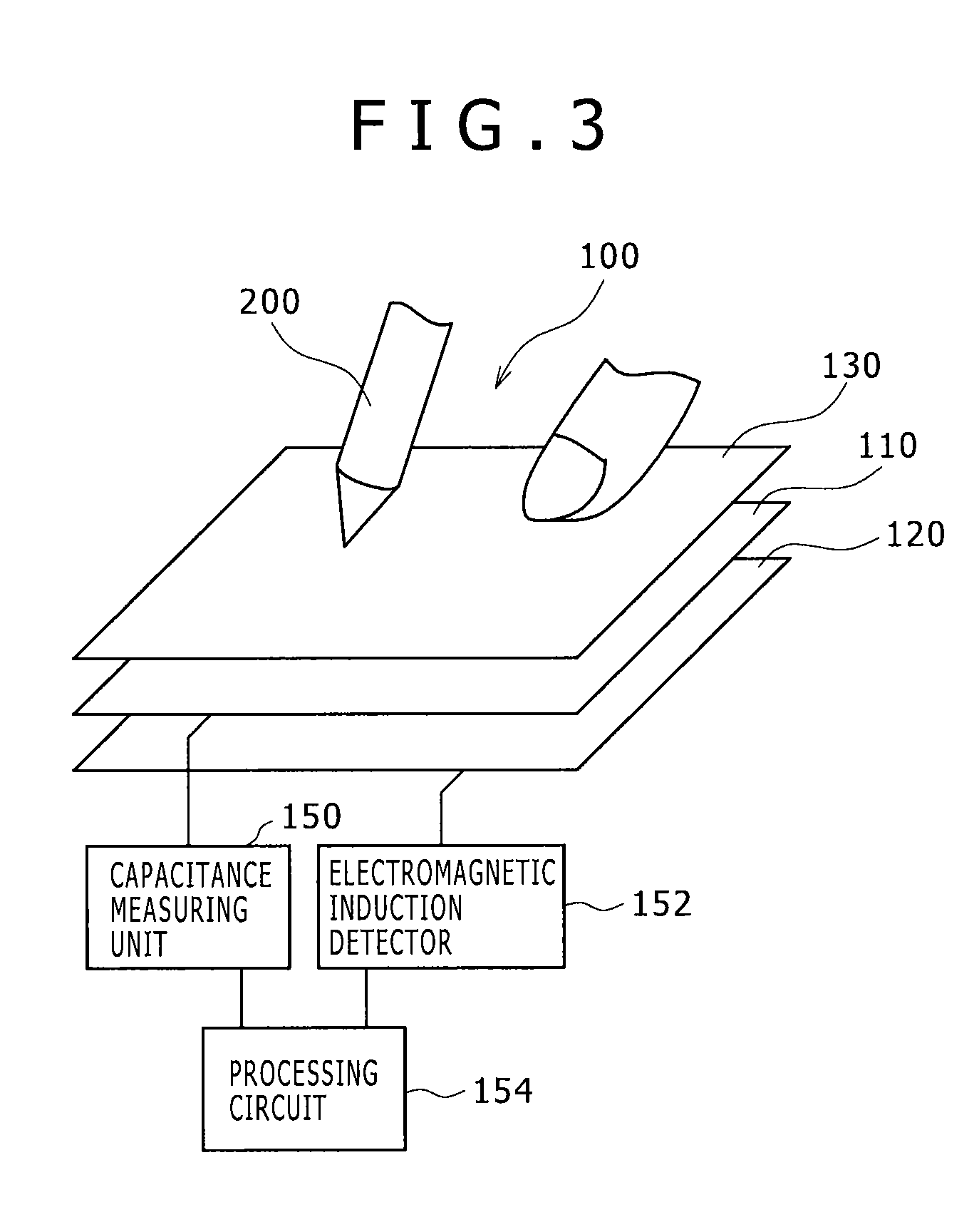
[0021]FIG. 1 is a plan view of the position detecting device according to one embodiment. FIG. 2 is an enlarged sectional view taken along line II-II of FIG. 1. The position detecting device 100 of the present embodiment is configured to detect a position indicated by part of the human body (e.g. a fingertip) or a position indicator 200 (FIG. 3). The position detecting device 100 includes a sensor substrate 110 serving as a first detector for performing position detection based on a capacitance system, and a magnetic flux detection substrate 120 serving as a second detector for performing position detection based on an electromagnetic induction system. The position detecting device 100 further includes a sheet member 130 covering the surface of the sensor substrate 110, a case 140 having a housing part 144 for housing the sensor substrate 110,...


PUM


Abstract

A position detecting device is disclosed, which detects a position indicated by a human body. The position detecting device includes: a sensor substrate including a detection area, in which a plurality of detection electrodes are formed, and a wiring area, in which wiring led out from the detection electrodes is formed, and a case configured to house the sensor substrate. The sensor substrate further includes a conductor, which is connected to a fixed potential, provided at a position opposed to (facing) the wiring area.

Description

CROSS-REFERENCE TO RELATED APPLICATION[0001]The present application claims the benefit under 35 U.S.C. §119(a) of Japanese Patent Application No. 2009-218229, filed, Sep. 21, 2009, the entire content of which is incorporated by reference herein.BACKGROUND OF THE INVENTION[0002]1. Field of the Invention[0003]The present invention relates to a position detecting device configured to perform position detection based on a capacitance system.[0004]2. Description of the Related Art[0005]There has been known a position detecting device formed by fitting an input unit into an opening part of a case. This input unit is configured by superposing a first detector of a capacitance system on a second detector of an electromagnetic induction system (refer to, e.g., Japanese Patent Laid-open No. 2009-162538, hereinafter referred to as patent document 1, pages 4 to 8, FIGS. 1 to 11). In this position detecting device, the position indicated by a part of the human body (e.g., a finger) is detected b...

Claims


Application Information

Patent Timeline
IPC IPC(8): G01B7/14G01R27/26
CPCG06F3/0416G06F3/046G06F3/044G06F3/0445G06F3/0446
Inventor YOKOTA, MASARUMUNAKATA, HIROSHI
Owner WACOM CO LTD
Why Eureka
Try Eureka