Image Interpolation for motion/disparity compensation

a technology of motion/disparity compensation and image interpolation, which is applied in image data processing, color television, television systems, etc., can solve the problems of so called blocking artifact appearance, high detrimental effect, and so called holes and overlaps, and achieve accurate estimation and reduce blocking artifacts

Inactive Publication Date: 2011-03-24
HER MAJESTY THE QUEEN & RIGHT OF CANADA REPRESENTED BY THE MIN OF IND THROUGH THE COMM RES CENT
View PDF3 Cites 46 Cited by
  • Summary
  • Abstract
  • Description
  • Claims
  • Application Information

AI Technical Summary

Benefits of technology

[0017]In accordance with the invention there is provided a new unidirectional motion-compensated frame interpolation method that addresses the problems of blocking artifacts, overlaps, and holes. Unidirectional motion field provides more accurate estimation of motion trajectories and information on occlusions than a bi-directional motion field. To reduce the blocking artifacts and solve the problem of holes and overlaps associated with a unidirectional motion field, the individual blocks of pixels are expanded and weighted before applying the unidirectional motion field. To fill holes, a new directional hole interpolation method is used. The advantages of these methods are their simplicity and effectiveness.

Problems solved by technology

The first problem is related to so called holes and overlaps.
The second problem is the appearance of so called blocking artifacts.
Broken lines, and the blocking visual defects in general, are easily noticeable by a human vision system and therefore are highly detrimental.
Most of these algorithms are quite complex, because the overlaps and holes are usually irregular in shape and size.
However, there are two essential performance problems associated with the bi-directional approach.
The first problem is the difficulty to accurately estimate the bi-directional motion since the pixels within the block to be interpolated are not known.
The second problem is the lack of information on occlusions.
The prior art is lacking a method of image interpolation that would provide fast and accurate image interpolation while reducing undesirable effects of holes, overlaps, and blocking artifacts in the interpolated image.

Method used


Image

  • Image Interpolation for motion/disparity compensation
  • Image Interpolation for motion/disparity compensation
  • Image Interpolation for motion/disparity compensation

Examples


Embodiment Construction

[0033]While the present teachings are described in conjunction with various embodiments and examples, it is not intended that the present teachings be limited to such embodiments. On the contrary, the present teachings encompass various alternatives, modifications and equivalents, as will be appreciated by those of skill in the art.

Description of Methods of the Invention

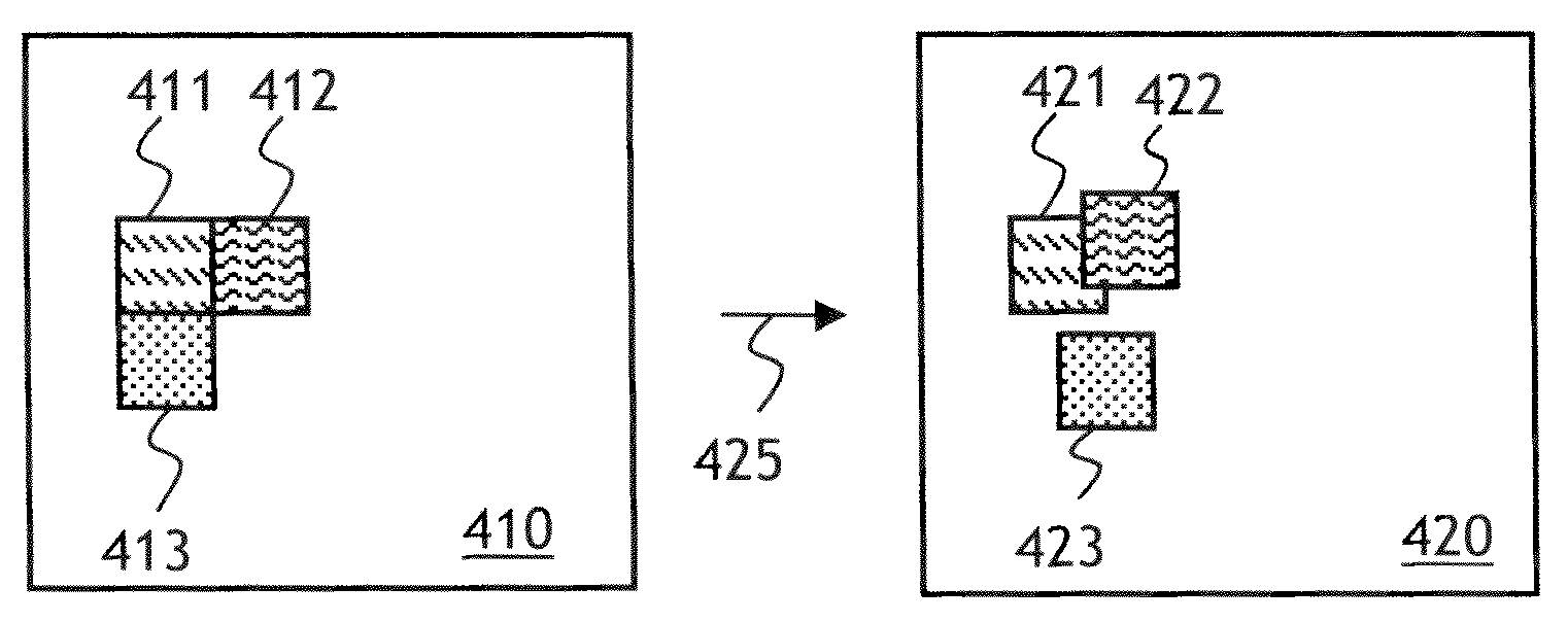
[0034]As noted above, a method of image interpolation of the invention is based on unidirectional motion fields between first and second images. Referring to FIG. 4A, a first image 410 is divided into contiguous blocks 411, 412, 413 . . . of pixels. Then, a forward motion field 425 in going from the first image 410 to a second image, not shown, is obtained using any suitable method of prior art. The forward motion field 425 includes a plurality of motion vectors, not shown. Each motion vector corresponds to a displacement of a particular one of the blocks 411, 412, 413 . . . in going from the first image 410 to the s...


PUM


Abstract

Methods of image interpolation disclosed herein include a method of irregular-grid expanded-block weighted motion compensation (IEWMC) and a method of block-wise directional hole interpolation (BDHI). The IEWMC can be used with unidirectional motion or disparity trajectories. The IEWMC can be applied in both forward and backward directions, and the interpolated images resulting from IEWMC application can be superimposed, or averaged, to reduce the blocking artifacts and handle the holes and overlaps. The BDHI takes into account the orientation of local edges and textures when filling the holes, which results in a sharper interpolated image.

Description

CROSS-REFERENCE TO RELATED APPLICATIONS[0001]The present invention claims priority from U.S. Appln No. 61 / 244,901 filed Sep. 23, 2009 which is incorporated herein by reference for all purposes.TECHNICAL FIELD[0002]The present invention relates to methods of image interpolation, and in particular to temporal interpolation for adjusting video frame rate, and / or to spatial interpolation for adjusting stereoscopic 3D effect.BACKGROUND OF THE INVENTION[0003]When a motion picture needs to be transmitted or displayed at a frame rate different from an original frame rate of the motion picture, or when a perceived depth of a stereoscopic image pair needs to be adjusted, a need arises to “interpolate” between two images. The term “image interpolation” refers to obtaining an image displaying objects, the shape, size, brightness, color, and / or position of which is intermediate between those of corresponding objects of the two known images.[0004]Temporal image interpolation is used in frame rate...

Claims


Application Information

Patent Timeline
Patent Type & Authority Applications(United States)
IPC IPC(8): H04N5/14
CPCH04N5/145G06T3/4007H04N13/0011H04N13/111
Inventor WANG, DEMINVINCENT, ANDREBLANCHFIELD, PHILIPKLEPKO, ROBERT
Owner HER MAJESTY THE QUEEN & RIGHT OF CANADA REPRESENTED BY THE MIN OF IND THROUGH THE COMM RES CENT
Why Eureka
Try Eureka