Cable clamp with clamping element
- Summary
- Abstract
- Description
- Claims
- Application Information
AI Technical Summary
Benefits of technology
Problems solved by technology
Method used
Image

Examples
Embodiment Construction
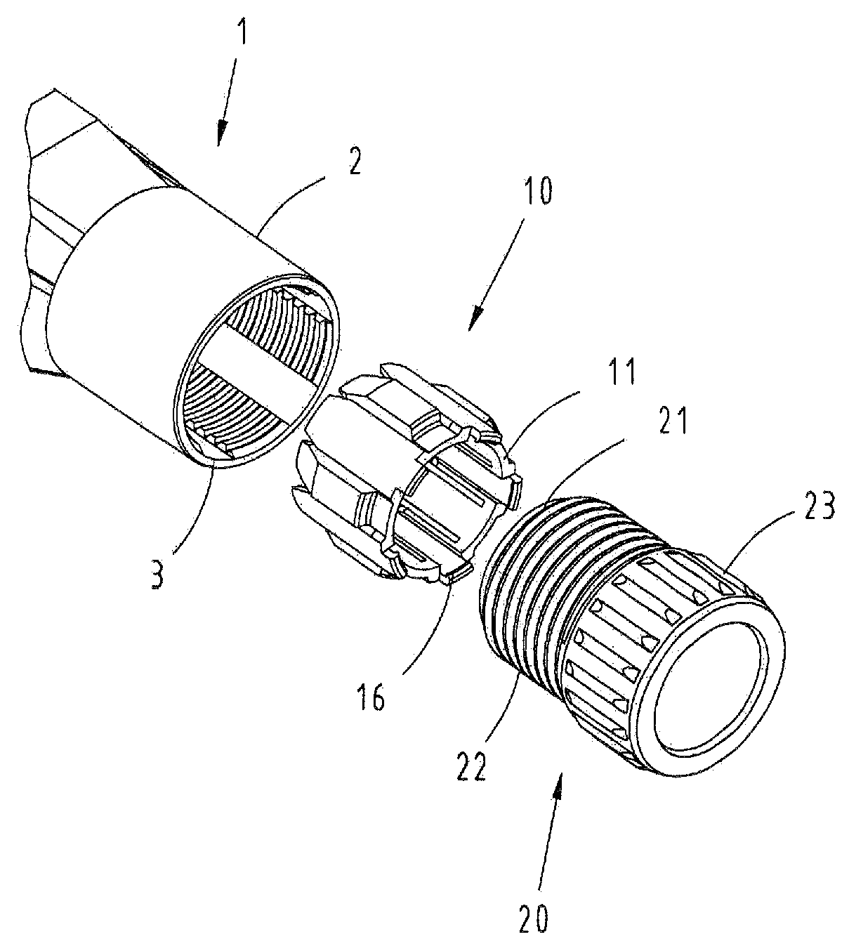
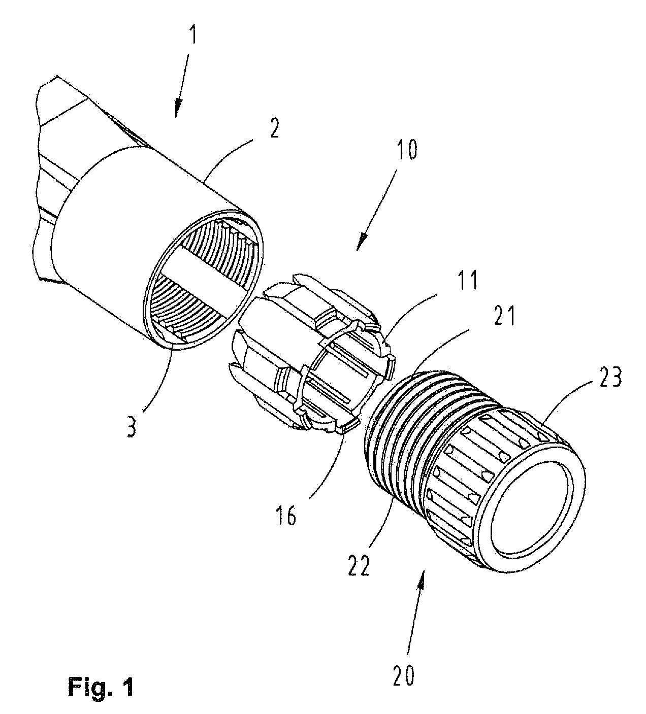
[0031]FIG. 1 shows a perspective representation of a connector housing 1 with a cable clamp. A mating region for accommodating contact elements is provided in the section of the connector housing 1 shown on the left, but not illustrated in detail. A cable receptacle 2 with a clamping element 10 positioned in front of its insertion end 3 and a pressure screw 20 is situated adjacent to said mating region.
[0032]The pressure screw 20 with the shape of a hollow cylinder essentially features a cylindrical thread 22 and a gripping region 23. A locating groove 21 provided for engaging the clamping element 10 therein is situated in front of the thread 22.
[0033]An electrical cable 8 to be connected is routed into the connector housing 1 through the pressure screw 20 and the clamping element 10.
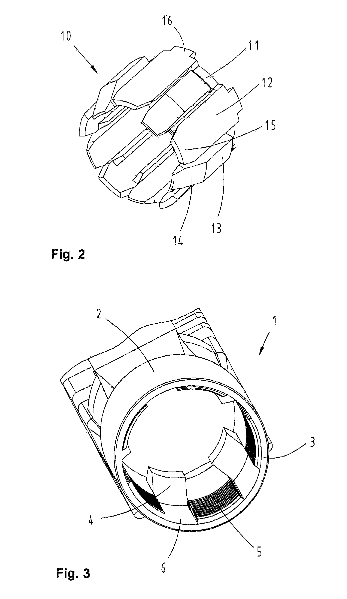
[0034]The clamping element 10 illustrated in FIG. 2 consists of five guiding fingers 12 and five clamping fingers 13 that are arranged axially and combined into a ring structure 11 on their end that fac...
PUM
 Abstract
Description
Claims
Application Information
 - R&D Engineer
- R&D Manager
- IP Professional
- Industry Leading Data Capabilities
- Powerful AI technology
- Patent DNA Extraction
Browse by: Latest US Patents, China's latest patents, Technical Efficacy Thesaurus, Application Domain, Technology Topic.
© 2024 PatSnap. All rights reserved.Legal|Privacy policy|Modern Slavery Act Transparency Statement|Sitemap