Eureka AIR delivers breakthrough ideas for toughest innovation challenges, trusted by R&D personnel around the world.

Tilt sensor

Inactive Publication Date: 2011-03-31
EVERLIGHT ELECTRONICS
View PDF10 Cites 8 Cited by
  • Summary
  • Abstract
  • Description
  • Claims
  • Application Information

AI Technical Summary

Benefits of technology

[0008]An aspect of the invention provides a tilt sensor for sensing a plurality of tilt directions that is thin, low cost, and easy to fabricate.
[0019]In one embodiment of the invention, based on how the first and second photosensitive devices receive the light beam, the tilt direction of the tilt sensor can be deduced. Moreover, since a moving thin-element less than or equal to 0.6 mm and larger than 0.1 mm thick is adopted, and the LED and the first and second photosensitive devices are die-bonded on a common plate, the thickness of the tilt sensor can be substantially reduced.

Problems solved by technology

These sensors are typically quite bulky.
Regarding the current consumer electronic products such as cellular phones, conventional tilt sensors may find difficulty for applications in such devices where a thin and sleek profile is usually preferable.
However, in this implementation, costs cannot be lowered, device bulk cannot be decreased, and fabrication steps cannot be reduced.
Accordingly, an important issue is to design a suitable tilt sensor which has small size and low cost, and is adaptable in consumer electronic products having a thin profile and low cost.

Method used


Image

  • Tilt sensor
  • Tilt sensor

Examples


Embodiment Construction

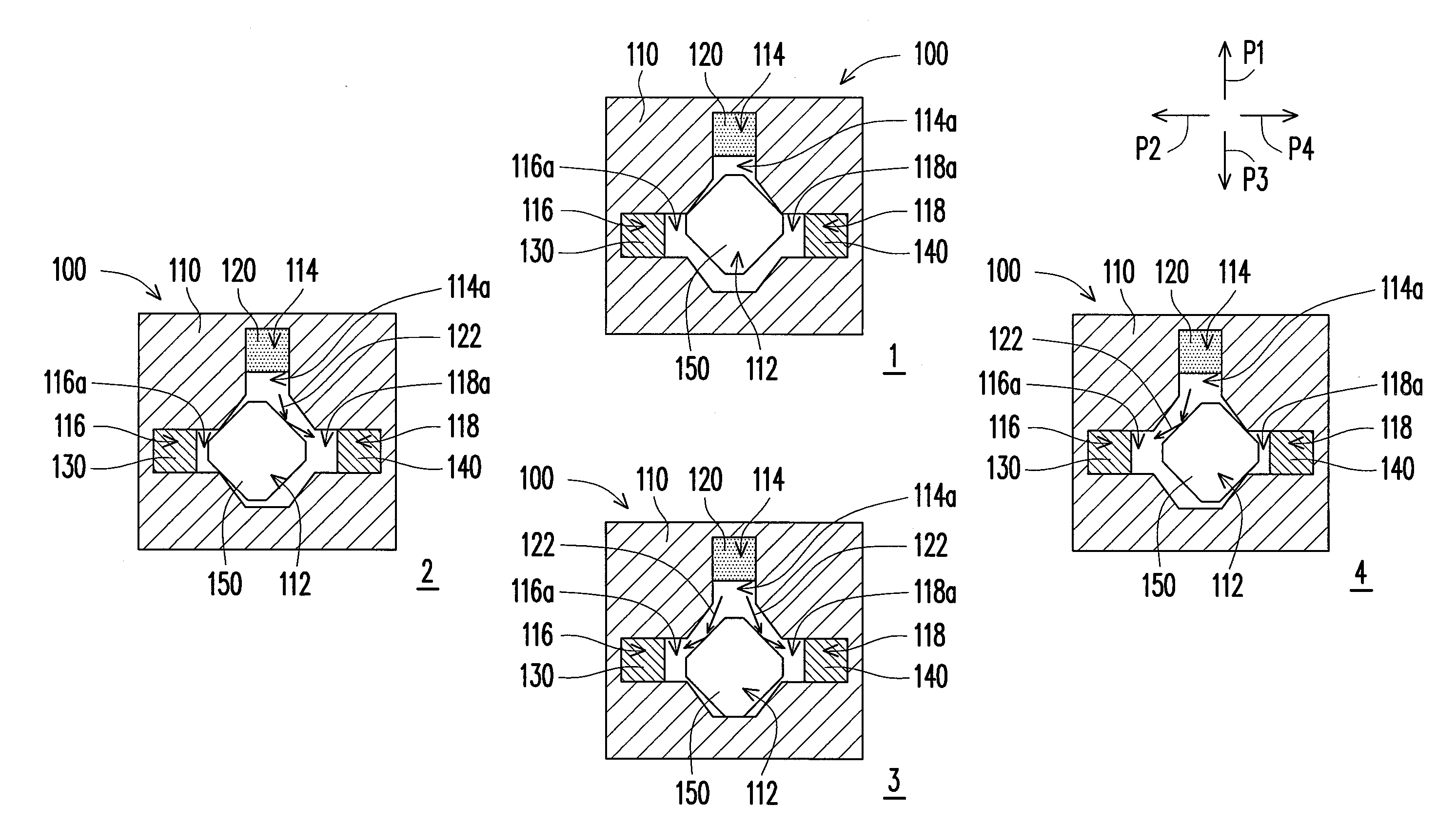
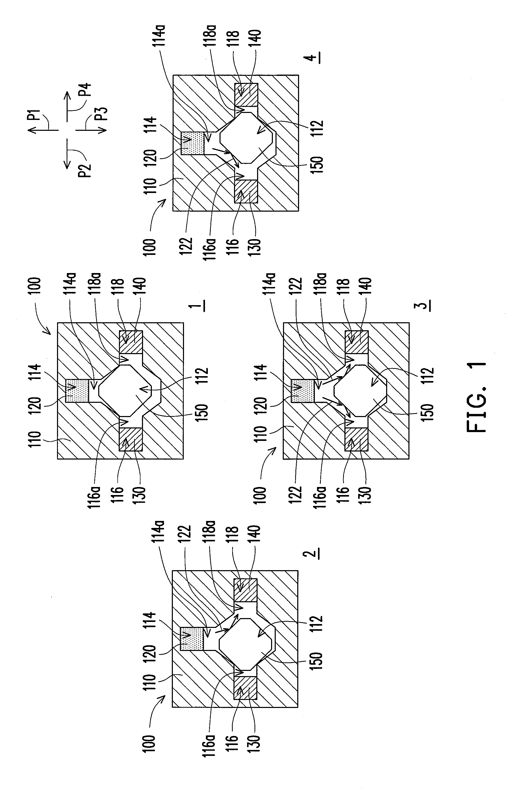
[0023]FIG. 1 is a schematic view illustrating a tilt sensor configured to sense different tilt directions in accordance with an embodiment of the invention. Referring to FIG. 1, a tilt sensor 100 according to the present embodiment includes a body 110, a light emitting device (LED) 120, a first photosensitive device 130, a second photosensitive device 140, and a moving thin-element 150.

[0024]The body 110 is suitable for tilting in a plurality of directions P1, P2, P3, and P4. The body 110 includes a movement region 112, a first containing region 114, a second containing region 116, and a third containing region 118. In particular, the first containing region 114 has a first opening 114a, and the first containing region 114 is connected with the movement region 112 through the first opening 114a. The second containing region 116 has a second opening 116a, and the second containing region 116 is connected with the movement region 112 through the second opening 116a. The third containi...


PUM


Abstract

A tilt sensor including a body, an LED, a first photosensitive device, a second photosensitive device, and a moving thin-element is provided. The body has a movement region, a first containing region, a second containing region, and a third containing region. The first, second, and third containing regions have an opening respectively and are connected with the movement region through the openings. The LED providing a light beam is disposed in the first containing region. The first and second photosensitive devices are disposed in the second and third containing regions respectively. When the body tilts toward different tilt directions, the moving thin-element moves in the tilt direction, allowing the light beam provided from the LED to reflect directly to the first and second photosensitive devices, or shielding the light beam provided from the LED from being transmitted to the first and second photosensitive devices.

Description

CROSS-REFERENCE TO RELATED APPLICATION[0001]This application claims the priority benefit of Taiwan application serial no. 98132756, filed on Sep. 28, 2009. The entirety of the above-mentioned patent application is hereby incorporated by reference herein and made a part of specification.BACKGROUND OF THE INVENTION[0002]1. Field of the Invention[0003]The invention generally relates to a sensor, and more particularly, to a tilt sensor.[0004]2. Description of Related Art[0005]Generally speaking, commercially available tilt sensors are usually dual-phase sensing, meaning the sensors can only sense two tilt directions. These sensors are typically quite bulky. Regarding the current consumer electronic products such as cellular phones, conventional tilt sensors may find difficulty for applications in such devices where a thin and sleek profile is usually preferable.[0006]Furthermore, if a quad-phase sensing tilt sensor is required, the four directions being up, down, left, and right, then u...

Claims


Application Information

Patent Timeline
IPC IPC(8): G01C9/06
CPCG01C9/10G01C9/06
Inventor LAI, LU-MING
Owner EVERLIGHT ELECTRONICS
Why Eureka
Eureka Blog
Learn More