
Electrode for Switch and Vacuum Switch, and Method of Manufacturing Electrode for Switch or Vacuum Switch

Inactive Publication Date: 2011-03-31
HITACHI LTD
View PDF11 Cites 4 Cited by
  • Summary
  • Abstract
  • Description
  • Claims
  • Application Information

AI Technical Summary

Benefits of technology

[0029]In accordance with the present invention, it is possible to provide the electrode or the switch which can improve a reliability of the switch, or the method of manufacturing the electrode for the switch or the vacuum switch.
[0030]Other objects, features and advantages of the invention will become apparent from the following description of the embodiments of the invention taken in conjunction with the accompanying drawings.BRIEF DESCRIPTION OF THE SEVERAL VIEWS OF THE DRAWING
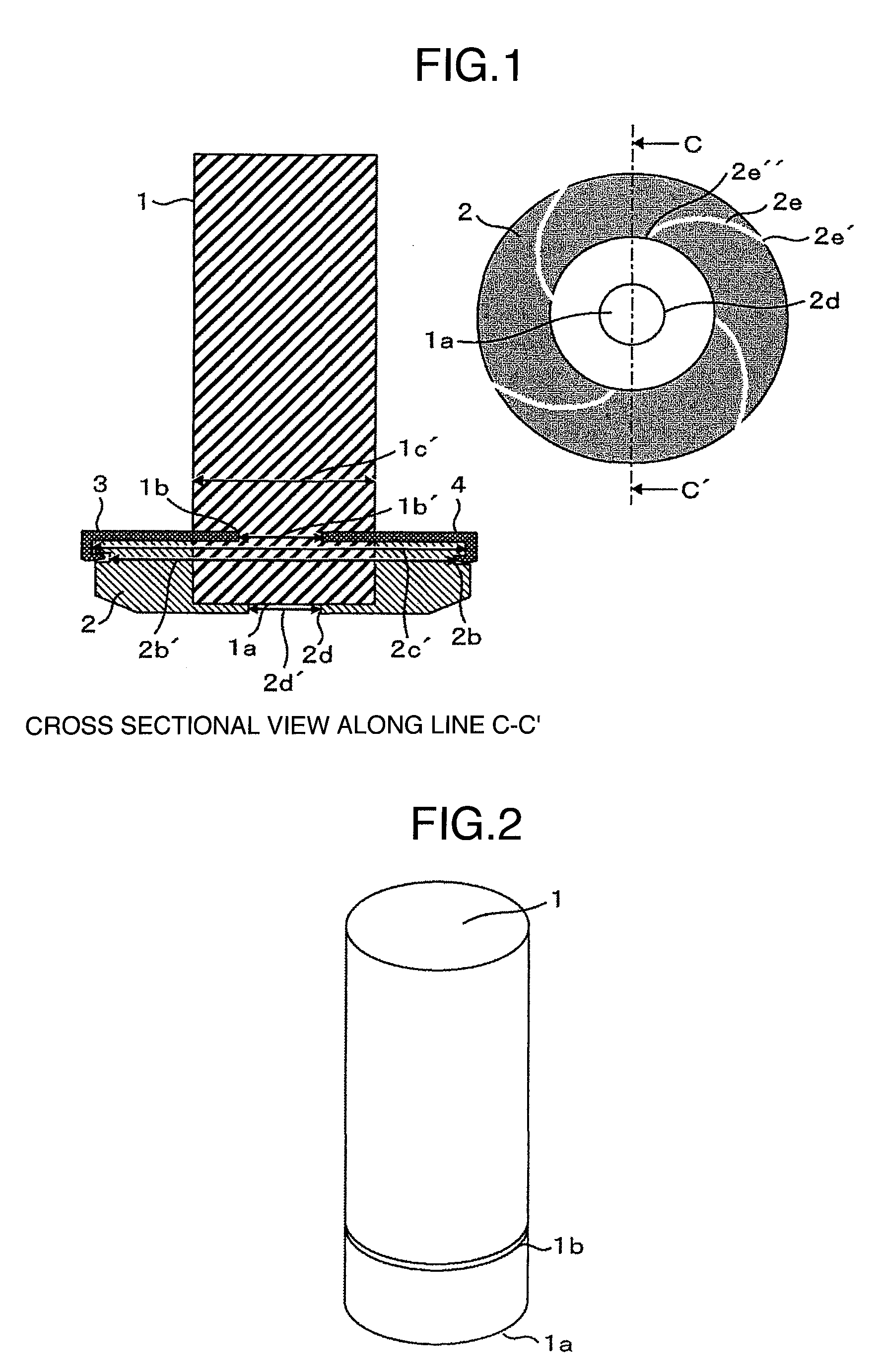
[0031]FIG. 1 is a cross sectional view in an axial direction of an electrode portion in accordance with a first embodiment;
[0032]FIG. 2 is a view showing a conductor rod in accordance with the first embodiment;
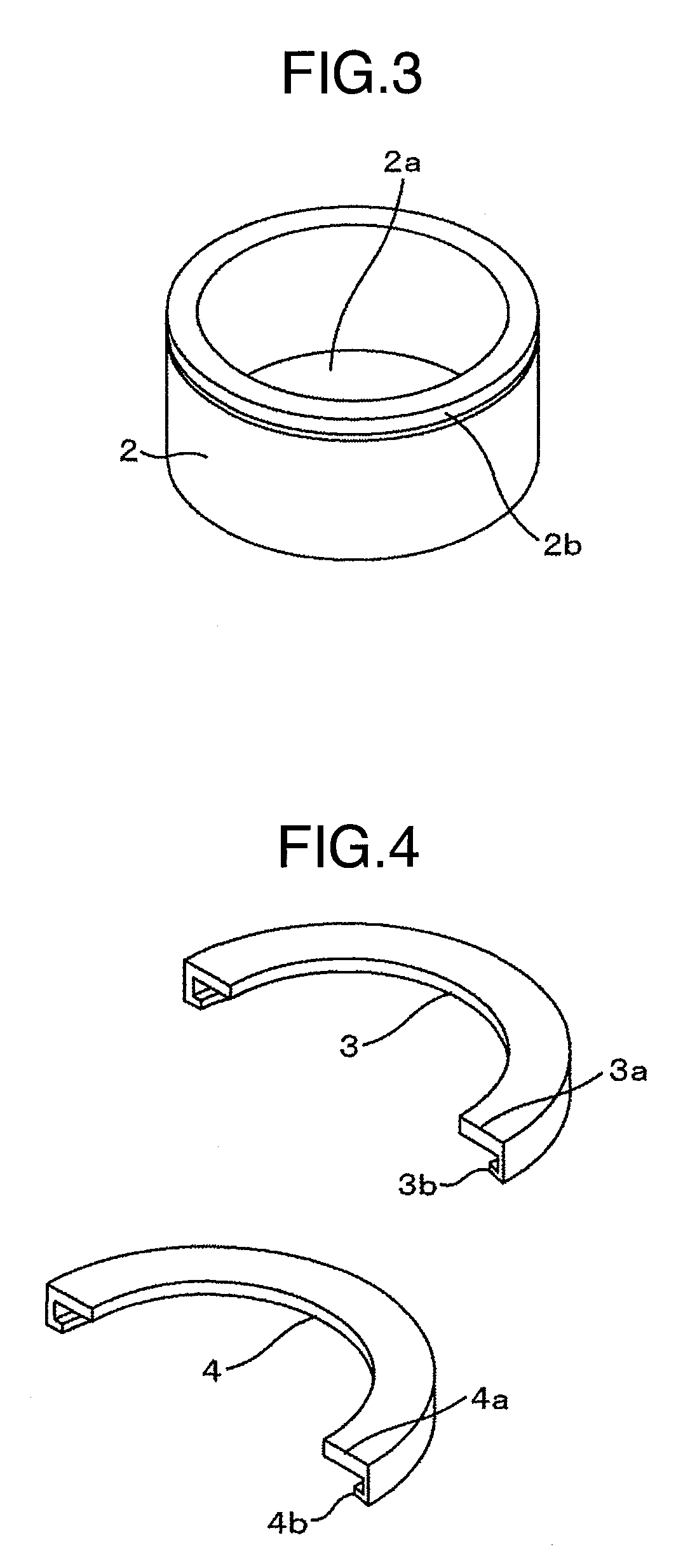
[0033]FIG. 3 is a view showing a contact point electrode in accordance with the first embodiment;
[0034]FIG. 4 is a view showing a coupling plate in accordance with the first embodiment;

Problems solved by technology

Further, since a coefficient of thermal conductivity is lower in the air gap portion (for example, filled with a vapor or a gas in the case of an air brake insulation switch, filled with a gas in the case of a gas insulation switch, and filled with a vacuum in the case of a vacuum insulation switch, respectively) in comparison with the electrode corresponding to the metal material, and a heat conduction is prevented in the air gap portion, the electrode coming to a high temperature at a time when the electric current is broken is hard to be radiated heat, and a possibility that the electrode member is molten becomes higher.
There is a risk that they cause a reduction of a reliability.
Accordingly, in the case of intending to fix the electrode rod and the electrode on the basis of a rotation, it is unavoidable that an air gap portion exists to some extent or is enlarged.

Method used


Image

  • Electrode for Switch and Vacuum Switch, and Method of Manufacturing Electrode for Switch or Vacuum Switch
  • Electrode for Switch and Vacuum Switch, and Method of Manufacturing Electrode for Switch or Vacuum Switch
  • Electrode for Switch and Vacuum Switch, and Method of Manufacturing Electrode for Switch or Vacuum Switch

Examples


first embodiment

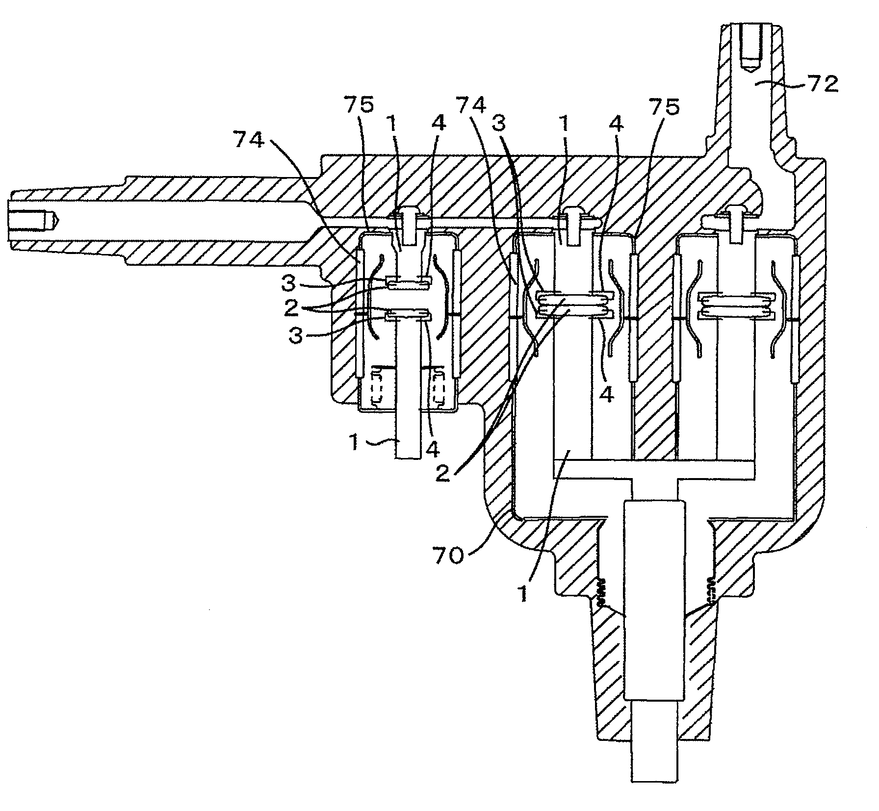
[0074]A description will be given of a first embodiment in accordance with the present invention. As shown in FIGS. 17 and 18, a vacuum switch gear in accordance with the present embodiment is mainly constructed by a vacuum switch 70, a cable 71 feeding an electric power to a load side, a bus bar 72 feeding an electric power to a vacuum switch, and an operation device 73 opening, closing and disconnecting the vacuum switch 70. Further, the vacuum switch 70 is constructed by an insulation tube 74 and a metal end plate 75, and is mainly constructed by a vacuum vessel in which an inner portion is set to vacuum, and conductor rods 1 and contact point electrodes 2 in a fixed side and a movable side which are connoted in the vacuum vessel.

[0075]As shown in FIG. 1, the cylindrical conductor rod 1 constructed by a copper member is inserted to an insertion hole corresponding to a shape of the conductor rod 1 provided in an inner side of the contact point electrode 2, and a first brazing fill...

second embodiment

[0084]Next, a description will be given of a second embodiment in accordance with the present invention with reference to FIGS. 8 to 16. In the present embodiment, the contact electrode 2 is provided with concave portions (grooves) 52c at two positions in an upper end portion of the electrode, as shown in FIG. 9. A convex portion 52b having no concavity is provided on the same circumference as the concave portion 52c. A groove 53 is formed on an outer peripheral surface of the concave portion 52b. Further, as shown in FIG. 10, the coupling plates 3 and 4 in the present embodiment are provided with a fitting portion 4c in such a manner as to correspond to the concave portion 52c of the contact point electrode 2, and a portion fitted to the conductor rod 1 is structured in the same manner as the first embodiment. Further, in the fitting portion 4c provided in the coupling plates 3 and 4, there is formed a groove 60 constructing the same circumference as the groove 53 formed in the con...


PUM

PropertyMeasurementUnit
Poweraaaaaaaaaa
Flexibilityaaaaaaaaaa
Transmissionaaaaaaaaaa

Abstract

An object of the invention is to provide a vacuum switch which can achieve a reduction of an electric loss and an improvement of a heat transmission performance by preventing an air gap portion from being generated between an electrode and a conductor rod and preventing the electrode and the conductor rod from generating any positional displacement. An electrode for a switch in accordance with the invention is provided with the conductor rod, a contact point electrode inserted to the conductor rod, and a coupling plate fixing both the elements to an outer side in a diametrical direction of the conductor rod and the contact point electrode, thereby fixing both the elements.

Description

BACKGROUND OF THE INVENTION[0001](1) Field of the Invention[0002]The present invention relates to an electrode for a switch and a vacuum switch, and a method of manufacturing the electrode for the switch or the vacuum switch.[0003](2) Description of Related Art[0004]Since the vacuum switch employs a vacuum insulation having a high insulation performance, and does not use a gas such as SF6 or the like having a high global warming coefficient, it is a switch which can achieve both downsizing and reduction of an environmental load.[0005]The vacuum switch carries out an electric current break or the like in an inner portion of a vacuum vessel, however, a method of manufacturing the vacuum vessel in a high vacuum exists as a method of manufacturing the vacuum vessel. In this case, in a brazing in a manufacturing step of the vacuum vessel, it is necessary to properly use a brazing filler metal in correspondence to a material between members constructing the vacuum vessel. Accordingly, it ...

Claims


Application Information

Patent Timeline
IPC IPC(8): H01H33/666H01H1/06H01H11/00
CPCH01H11/041H01H11/045Y10T29/49105H01H33/6643H01H33/664H01H33/66H01H33/66207
Inventor YAMAZAKI, MIKITSUCHIYA, KENJIMORITA, AYUMUKOBAYASHI, MASATOKIKUKAWA, SHUICHIKIKUCHI, SHIGERU
Owner HITACHI LTD
Learn More