

Pseudo-differential receiving circuit
a receiving circuit and pseudodifferential technology, applied in the direction of digital transmission, electronic switching, pulse technique, etc., can solve the problem that the pseudodifferential transmission method suffers from internal crosstalk
- Summary
- Abstract
- Description
- Claims
- Application Information
AI Technical Summary
Problems solved by technology
Method used
Image

Examples
first embodiment
Best Mode
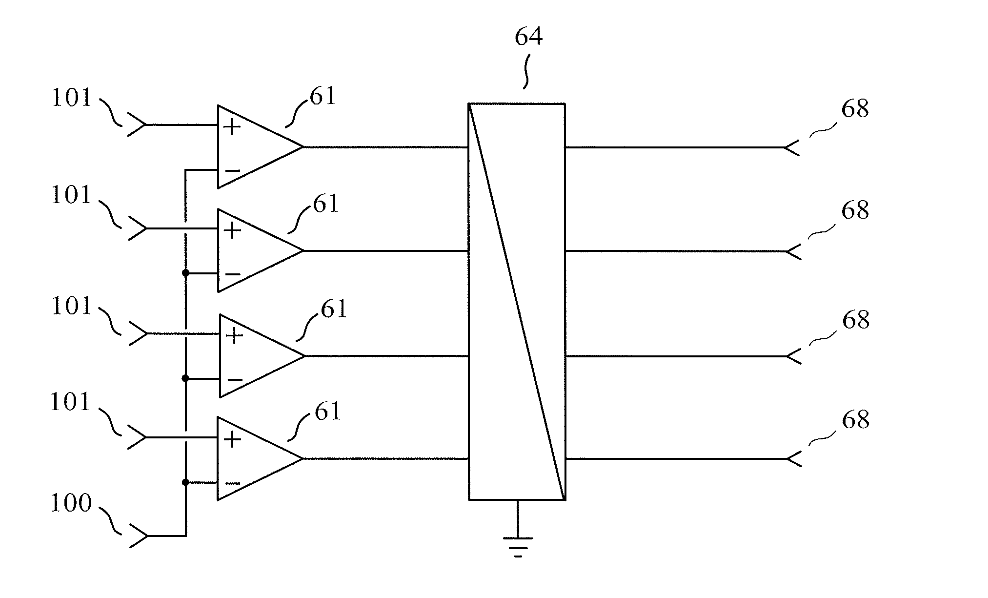
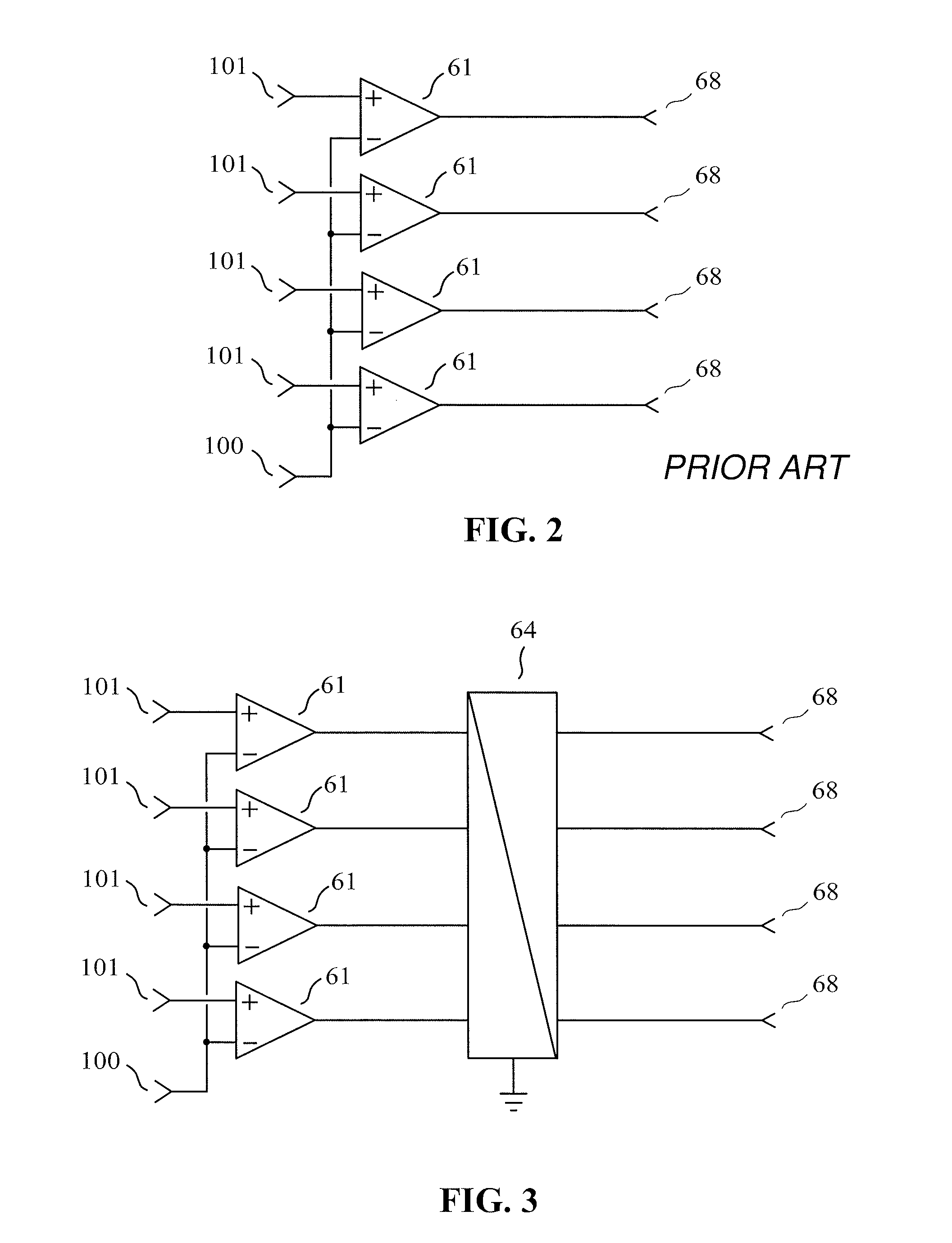
[0056]As a first embodiment of a receiving circuit of the invention, given by way of non-limiting example and best mode of carrying out the invention, we have represented in FIG. 3 a receiving circuit of the invention built inside an integrated circuit, comprising m=4 signal terminals (101) and a common terminal (100), the signal terminals (101) and the common terminal (100) being intended to be connected to an interconnection having m=4 transmission conductors.
[0057]The receiving circuit shown in FIG. 3 is such that:
[0058]each of the p=4 “output signals of the receiving circuit” is delivered to an output (68) which is a single-ended output;
[0059]each of the p outputs (68) corresponds to an output of a combining circuit (64) having m inputs and p outputs;
[0060]each of the m=4 signal terminals (101) is connected to a first input terminal of a differential circuits (61), said differential circuit also having a second input terminal and a single output terminal;
[0061]the commo...
second embodiment
[0069]As a second embodiment of a receiving circuit of the invention, given by way of non-limiting example, we have represented in FIG. 4 a receiving circuit of the invention built inside an integrated circuit, comprising m=4 signal terminals (101) and a common terminal (100), the signal terminals (101) and the common terminal (100) being intended to be connected to an interconnection having m=4 transmission conductors. The receiving circuit shown in FIG. 4 is such that:
[0070]each of the p=4 “output signals of the receiving circuit” is delivered to an output (68) which is a single-ended output;
[0071]each of the p outputs (68) corresponds to an output of a combining circuit (64) comprising p active sub-circuits (641) and a feedback network (642), said combining circuit (64) having m inputs and p outputs;
[0072]each of the m=4 signal terminals (101) is connected to a first input terminal of a differential circuits (61), said differential circuit also having a second input terminal and ...
third embodiment
[0080]As a third embodiment of a receiving circuit of the invention, given by way of non-limiting example, we have represented in FIG. 5 a receiving circuit of the invention, comprising m=3 signal terminals (101) and a common terminal (100), the signal terminals (101) and the common terminal (100) being intended to be connected to an interconnection having m=3 transmission conductors. The receiving circuit shown in FIG. 5 is such that:
[0081]each of the p=3 “output signals of the receiving circuit” is delivered to an output (68) which is a differential output comprising 2 terminals (681) (682);
[0082]each of the p outputs (68) corresponds to an output of a combining circuit (64) having m inputs and p outputs;
[0083]each input of said combining circuit (64) corresponds to the output of a differential circuit comprising a differential pair made of two transistors (611) (612), a current source (613) and two resistors (618) (619);
[0084]each of the m=3 signal terminals (101) is connected to...
PUM
 Abstract
Description
Claims
Application Information