Puncture needle assembly and medicinal liquid injector

a technology of injector and needle, which is applied in the direction of infusion needle, infusion syringe, other medical devices, etc., can solve the problem of finger or the like being mistakenly pierced

Active Publication Date: 2011-03-31
TERUMO KK
View PDF22 Cites 26 Cited by
  • Summary
  • Abstract
  • Description
  • Claims
  • Application Information

AI Technical Summary

Problems solved by technology

Therefore, in the case that such a pushing force is unintentionally exerted on the inside member, the inside member is brought into the second st

Method used


Image

  • Puncture needle assembly and medicinal liquid injector
  • Puncture needle assembly and medicinal liquid injector
  • Puncture needle assembly and medicinal liquid injector

Examples


first embodiment

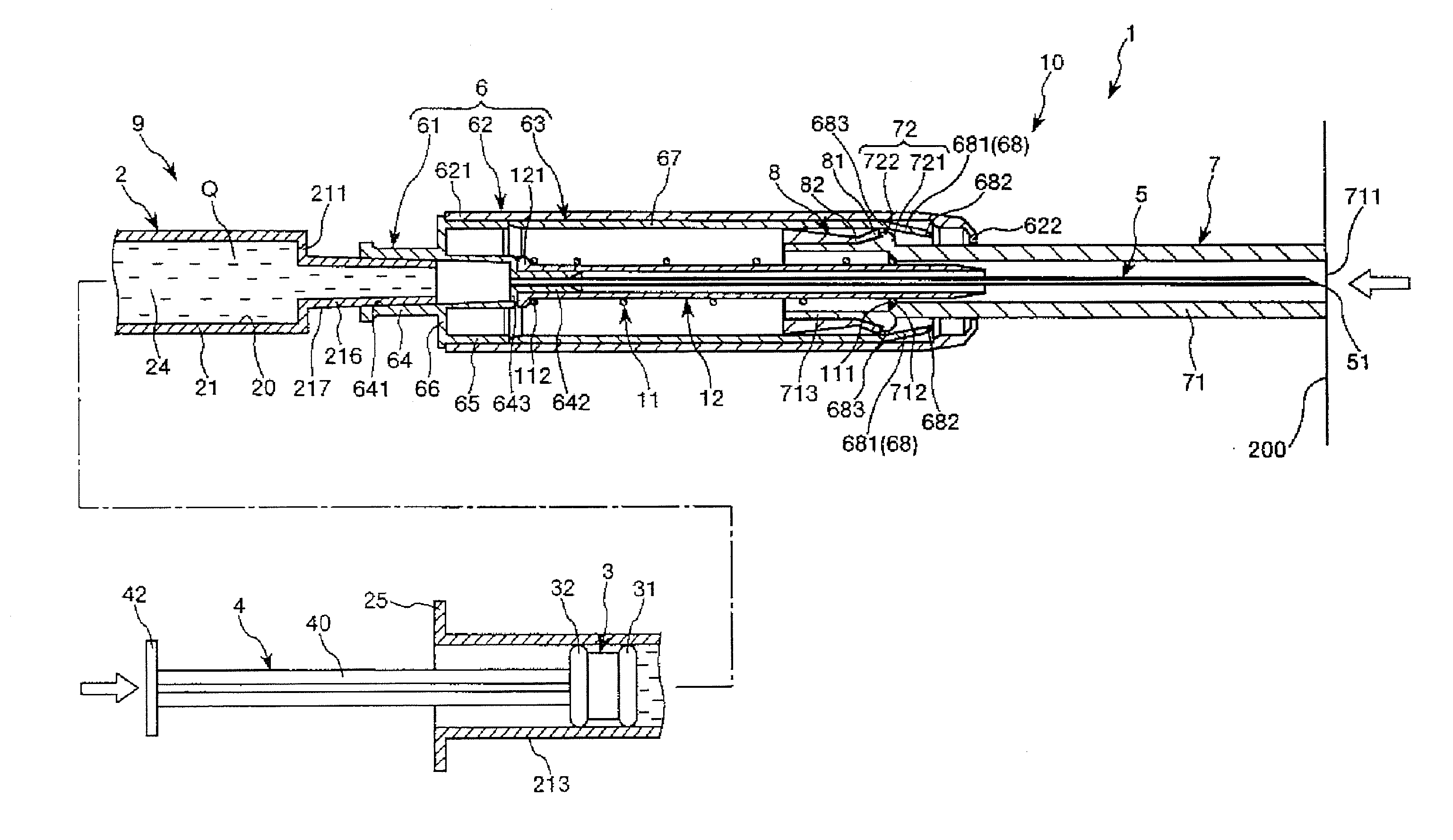
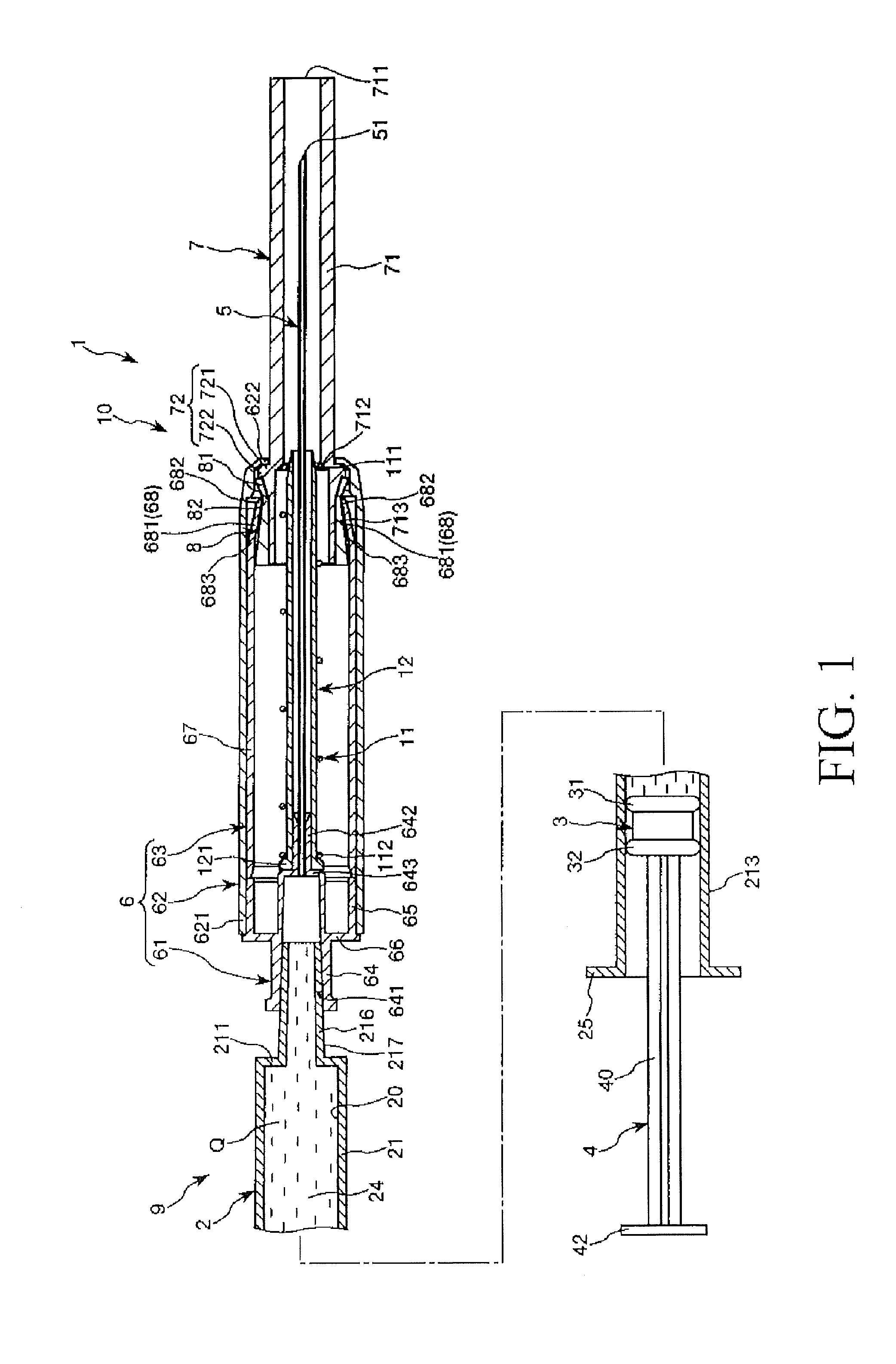
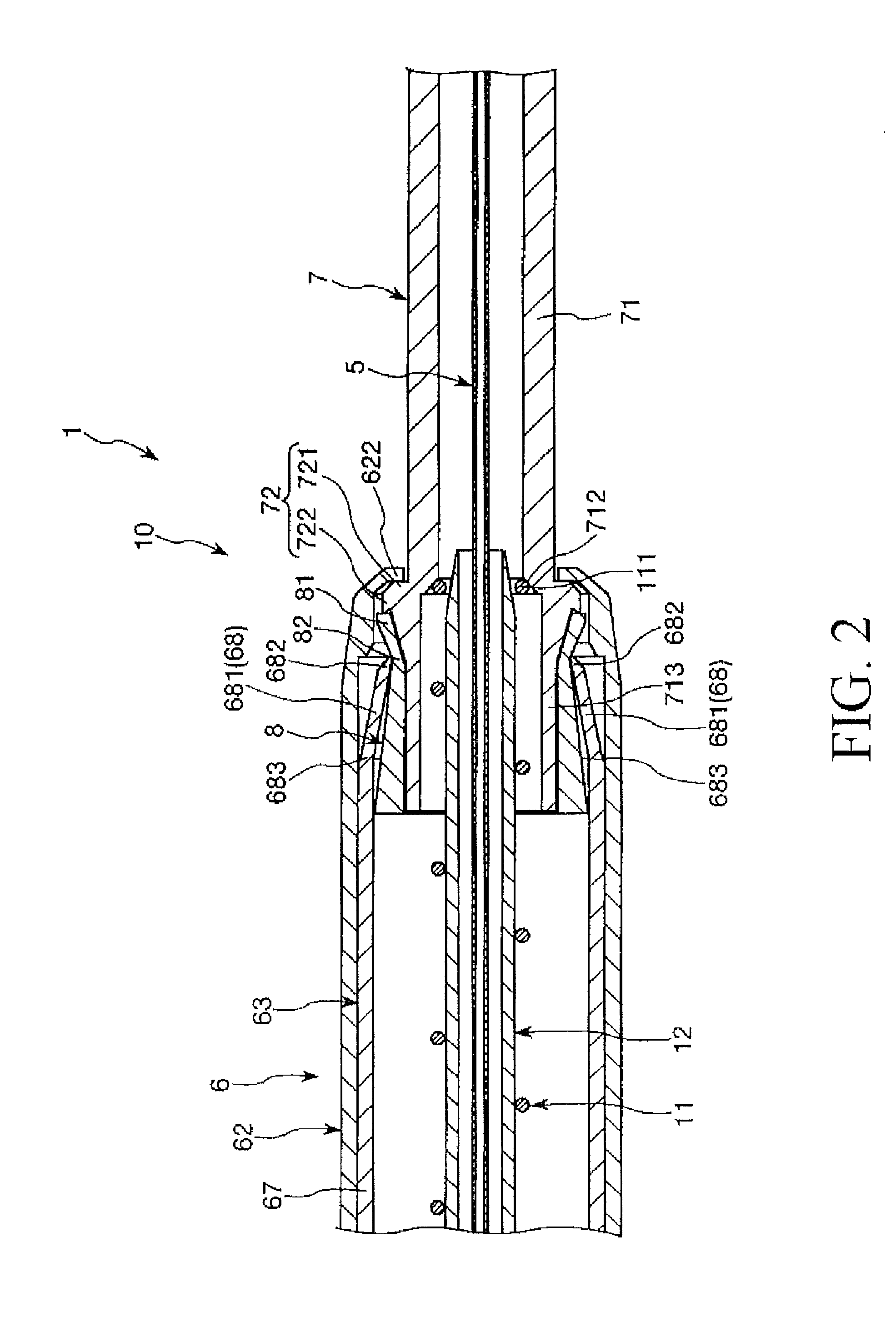
FIG. 1 is a longitudinal sectional view sequentially illustrating states during use of a first embodiment of the medicinal liquid injector (puncture needle assembly) according to the present invention. FIG. 2 is a longitudinal sectional view showing, in an enlarged form, a major part of the medicinal liquid injector shown in FIG. 1. FIGS. 3 to 6 are longitudinal sectional views sequentially illustrating states during use of the medicinal liquid injector shown in FIG. 1. FIG. 7 is a longitudinal sectional view illustrating a condition in which use of the medicinal liquid injector shown in FIG. 1 is stopped halfway. Incidentally, in the following explanations, to facilitate descriptions thereof, the left side in FIGS. 1 to 7 will be referred to as a “base end (proximal end)”, while the right side will be referred to as a “distal end.”

The medicinal liquid injector 1 shown in each of the drawings is composed of a syringe (container) 9 prefilled with a medicinal liquid Q, and a puncture ...

second embodiment

FIG. 8 is a longitudinal sectional view sequentially illustrating states during use of a second embodiment of the medicinal liquid injector (puncture needle assembly) according to the present invention. FIG. 9 is a longitudinal sectional view showing, in an enlarged form, a major part of the medicinal liquid injector shown in FIG. 8. FIGS. 10 to 12 are longitudinal sectional views sequentially illustrating states during use of the medicinal liquid injector shown in FIG. 8. Incidentally, in the following explanations, for facilitating descriptions thereof, the left side in FIGS. 8 to 12 will be referred to as a “base end (proximal end)” and the right side will be referred to as a “distal end.”

Next, a second embodiment of the invention will be described. Descriptions thereof will center on differences from the first embodiment described above, and descriptions of the same items will be omitted.

In a medicinal liquid injector 1 (puncture needle assembly 10) according to the second embod...

third embodiment

FIG. 13 is a longitudinal sectional perspective view showing an unused state of a third embodiment of the medicinal liquid injector (puncture needle assembly) according to the present invention. FIG. 14 is a view (side view) of the medicinal liquid injector shown in FIG. 13, as viewed in a direction along the arrow A. FIG. 15 is a longitudinal sectional perspective view showing a used state of the third embodiment of the medicinal liquid injector (puncture needle assembly) according to the present invention. FIG. 16 is a view (side view) of the medicinal liquid injector shown in FIG. 15, as viewed in a direction along the arrow B. Incidentally, in the following explanations, for facilitating descriptions thereof, the upper side in FIGS. 13 to 16 will be referred to as a “distal end” and the lower side will be referred to as a “base end (proximal end).”

Next, referring to these figures, a third embodiment of the puncture needle assembly and the medicinal liquid injector according to t...


PUM


Abstract

A puncture needle assembly has a needle tube, a protector capable of moving between a first position at which the protector covers the tip of the needle tube and a second position at which the tip is exposed, a body for movably supporting the protector and having an elastic deformable section, and an engagement preventing member removably mounted to the base end of a protector body. The protector has a rib. A portion on the head end side of the rib forms a contact section, and a portion on the base end side of the rib forms an engaging section engaging with the elastic deformable section. When the protector moves from the first position to the second position, the engagement preventing member moves together with the protector to prevent the engaging section from engaging with the elastic deformable section and elastically deforms the elastic deformable section.

Description

TECHNICAL FIELDThe present invention relates to a puncture needle assembly and a medicinal liquid injector provided with the same.BACKGROUND ARTPrefilled syringes, each of which is preliminarily filled with a medicinal liquid, have been known. Such prefilled syringes each include an outer tube provided with a discharge port at its distal end, a gasket inserted into the outer tube, and a plunger connected to the gasket. The medicinal liquid is enclosed in a space surrounded by the outer tube and the gasket.In the case of injecting a medicinal liquid, for example, into a living body by use of the prefilled syringe, a needle assembly having a hollow needle is mounted on the discharge port of the outer tube, whereby the prefilled syringe is used in such a mounted condition (see, for example, Patent Document 1). Further, in the mounted condition, the inside of the outer tube communicates with the inside of the hollow needle. The needle assembly (protective sleeve) described in Patent Doc...

Claims


Application Information

Patent Timeline
IPC IPC(8): A61M5/32A61M5/50
CPCA61M5/28A61M5/326A61M2205/583A61M2005/3247A61M2005/3267A61M5/5086
Inventor TAKEMOTO, MASAFUMI
Owner TERUMO KK
Why Eureka
Try Eureka