Method and apparatus using deliquescent filter for separating mixture

a technology of deliquescent filter and mixture, which is applied in the direction of crystallization separation, separation process, centrifuge, etc., can solve the problems of corruption and deterioration of natural products and the like, and achieve the effect of preventing the formation of a slurry and a separation of slurry

Active Publication Date: 2011-04-07
JO
View PDF60 Cites 12 Cited by
  • Summary
  • Abstract
  • Description
  • Claims
  • Application Information

AI Technical Summary

Benefits of technology

[0029]1. A filter medium and a captured material are separated by melting the filter

Problems solved by technology

1. A filter medium and a captured material are separated by melting the filter medium. Thus, the capturing material and the captured material are easily separated.
2. Further, when

Method used


Image

  • Method and apparatus using deliquescent filter for separating mixture
  • Method and apparatus using deliquescent filter for separating mixture
  • Method and apparatus using deliquescent filter for separating mixture

Examples


Embodiment Construction

1. Outlines of Apparatuses

[0044]Outlines of apparatuses constituting a system are described.

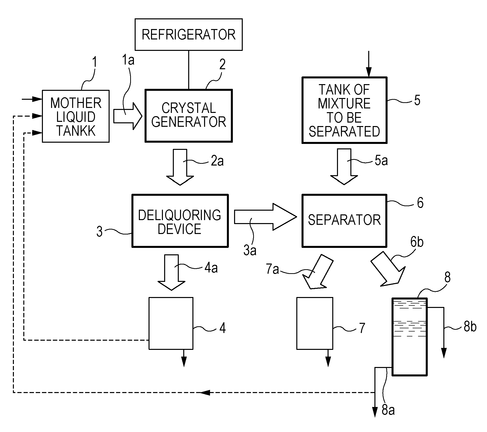
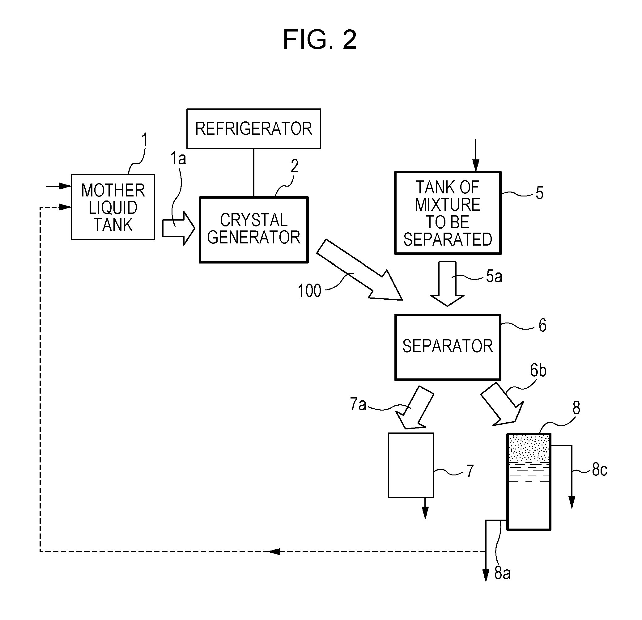
[0045]FIGS. 1 and 2 show typical examples of a system for separating a mixture to be separated using a deliquescent filter medium. A system shown in FIG. 1 is a system including a crystal generator 2, a deliquoring device 3, a separator 6, and a melting tank 8. A system shown in FIG. 2 is a system including a crystal generator 2, a separator 6, and a melting tank 8. In the present invention, such a system may be installed in a cooling environment such as a cooling room or chamber.

[0046]Each of the apparatuses constituting the systems is described below.

1) Crystal Generator 2

[0047]The crystal generator 2 is an apparatus for forming mother liquid crystals 2a. The crystal generator 2 produces the mother liquid crystals 2a by cooling a mother liquid 1a.

[0048]The mother liquid crystals 2a are crystals, a mixture of crystals and the mother liquid 1a, filter crystals 100, or a mixture of the filter...


PUM

PropertyMeasurementUnit
Temperatureaaaaaaaaaa
Centrifugal forceaaaaaaaaaa
Viscosityaaaaaaaaaa

Abstract

The present invention provides a method and apparatus for separating a mixture to be separated (solid-liquid or liquid-liquid mixture) using a deliquescent filter medium. The mixture to be separated is separated into a liquid passing through a filter layer of the filter medium and a captured material captured in the filter layer.

Description

TECHNICAL FIELD[0001]The present invention relates to a technique for separating a liquid / liquid mixture or a liquid / solid mixture.BACKGROUND ART[0002]A technique for separating liquid / liquid mixtures and solid / liquid mixtures includes filtration (Perry Robert H. Perry's Chemical Engineers' Handbook, 6th ed., pp. 19.65-19.89, 1984) (this hand book is referred to as the “Perry document” hereinafter). In the filtration, a mixture to be separated (solid-liquid mixture or liquid-liquid mixture) is supplied to a filter layer made of a porous material (diatomaceous earth), a fibrous material, or the like, and a liquid is passed through the filter layer due to differential pressure (such as centrifugal force) while a solid is captured in the filter layer. Alternatively, a low-viscosity liquid is passed through the filter layer, while a high-viscosity liquid and / or a solid are captured in the filter layer and separated. With respect to the low-viscosity liquid and the high-viscosity liquid,...

Claims


Application Information

Patent Timeline
IPC IPC(8): B01D9/04
CPCB01D9/004B01D17/08B04B15/10B04B7/18B04B3/00
Inventor TEDUKA, MASAHIROJO, MASAHARU
Owner JO
Why Eureka
Try Eureka