Fault detection using phase comparison

a phase comparison and fault technology, applied in the field of system and method of communicating power system information, can solve the problems of insufficient data reporting of prior art fault circuit indication systems, no indication from conventional wireless devices, and still substantial amounts of time and money spent by electric utilities to determin

Active Publication Date: 2011-04-07
SCHWEITZER ENGINEERING LABORATORIES
View PDF9 Cites 33 Cited by
  • Summary
  • Abstract
  • Description
  • Claims
  • Application Information

AI Technical Summary

Problems solved by technology

Nonetheless, electrical utilities still spend substantial amounts of time and money determining the locations of faults on their networks.
The radio interface unit is often located in proximity to an FCI within an underground vault, which is susceptible to external elements.
Prior art fault circuit indication systems have further been found to be insufficient in their reporting of data.
However, conventional wireless devices provide no indication as to whether a particular faulted circuit indicator is actually connected to the radio interface unit.
In addition, prior art devices do not display the status of a plurality of or multi

Method used


Image

  • Fault detection using phase comparison
  • Fault detection using phase comparison
  • Fault detection using phase comparison

Examples


Embodiment Construction

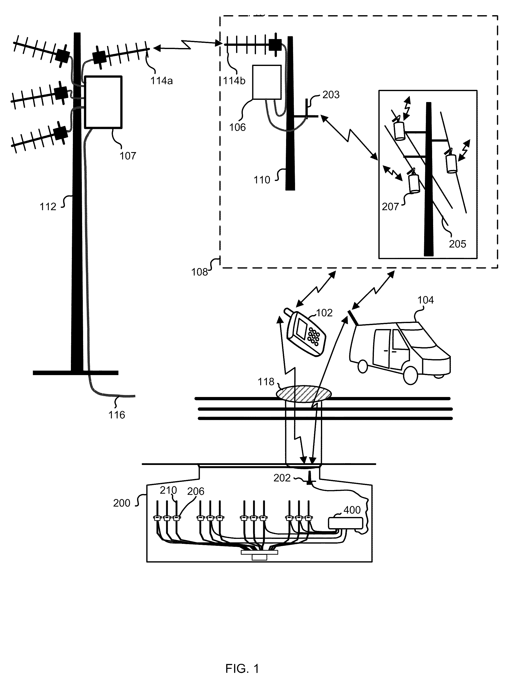
[0061]FIG. 1 illustrates a faulted circuit indicator monitoring system in accordance with an aspect of the present invention. A number of overhead faulted circuit indicators 207 each contain a two-way radio that communicates the occurrence of a fault via a short range antenna 203 to a local site 110 having an intelligent module 106 installed within radio range of the faulted circuit indicators 207. The intelligent module then uses the existing wired telephone network (not shown) to communicate the fault occurrence to a remote site 112. Alternatively, the intelligent module may include a radio interface unit associated therewith for communication with an antenna 114b to communicate the fault occurrence to a remote site 112 having another long range RF antenna 114a. The remote site 112 includes a remote intelligent module 107, which may be connected to another site (not shown) via a wired connection 116. When a fault is detected by a faulted circuit indicator, the occurrence is relaye...


PUM


Abstract

A system for communicating information between a detection device and a wireless device is provided. The system generally includes a detection device adapted to monitor a condition related to a power system. A radio interface unit is in communication with the detection device via a communication member. A wireless device is further provided which is in radio communication with the radio interface unit such that the detection device communicates information to the wireless device through a radio interface unit. The system's components are further adapted to endure harsh conditions (e.g., prolonged exposure to water).

Description

CROSS-REFERENCE TO RELATED APPLICATIONS[0001]This application also claims benefit under 35 U.S.C. §119(e) of U.S. Provisional Application entitled “FAULT LOCATION USING PHASE COMPARISON,” filed on Oct. 19, 2009, having the Ser. No. 61 / 252,768, and is a continuation-in-part application of U.S. patent application entitled “SYSTEM AND METHOD FOR COMMUNICATING POWER SYSTEM INFORMATION THROUGH A RADIO FREQUENCY DEVICE,” filed on May 18, 2007, having the Ser. No. 11 / 750,962, which claims benefit under 35 U.S.C. §119(e) of U.S. Provisional Application entitled “SYSTEM AND METHOD FOR COMMUNICATING POWER SYSTEM INFORMATION THROUGH A RADIO FREQUENCY DEVICE,” filed on May 19, 2006, having Ser. No. 60 / 801,757, naming Edmund O. Schweitzer, III, Mark J. Bosold, Douglas A. Park, Laurence Virgil Feight, and Adam Thomas Belote, as inventors, the complete disclosure thereof being incorporated by reference.FIELD OF THE INVENTION[0002]The present invention relates generally to a system and method for c...

Claims


Application Information

Patent Timeline
IPC IPC(8): G08B1/08
CPCG01R31/085H02G1/02H02J13/0075H04Q9/00H04Q2209/883Y02E60/74H04Q2209/40H04Q2209/75Y04S10/30H02J13/00002H02J13/00017H02J13/00024H02J13/00026Y02E60/00
Inventor SCHWEITZER, III, EDMUND O.WHITEHEAD, DAVID E.
Owner SCHWEITZER ENGINEERING LABORATORIES
Why Eureka
Try Eureka