Eureka AIR delivers breakthrough ideas for toughest innovation challenges, trusted by R&D personnel around the world.

Fluid flow modification apparatus

a technology of flow field and apparatus, which is applied in mechanical equipment, transportation and packaging, mixing, etc., can solve the problems of relatively complex and bulky smv® gas mixer, and achieve the effects of less bulky and complex, improved mixing, and greater mixing

Inactive Publication Date: 2011-04-07
IMPERIAL INNOVATIONS LTD
View PDF2 Cites 21 Cited by
  • Summary
  • Abstract
  • Description
  • Claims
  • Application Information

AI Technical Summary

Benefits of technology

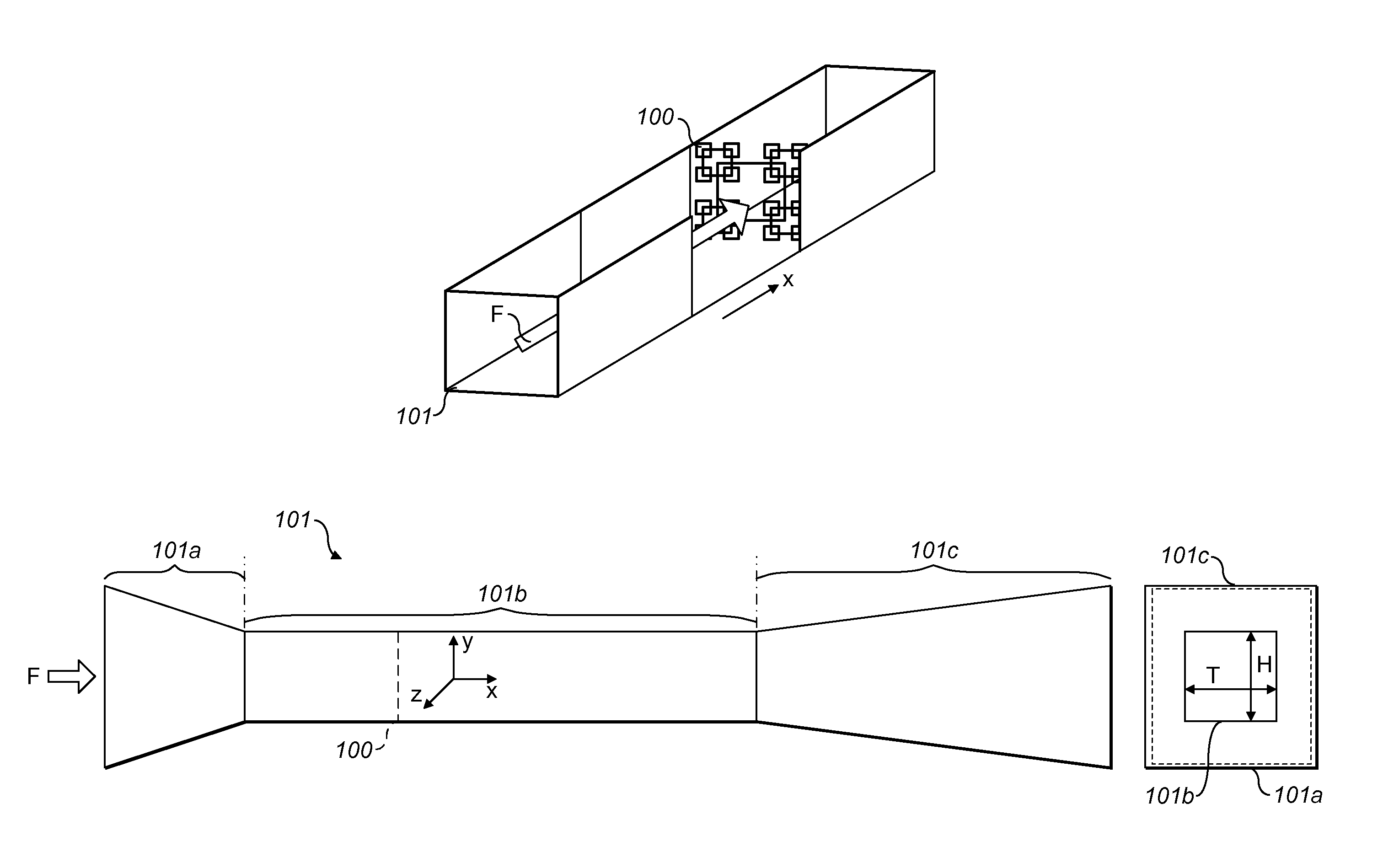
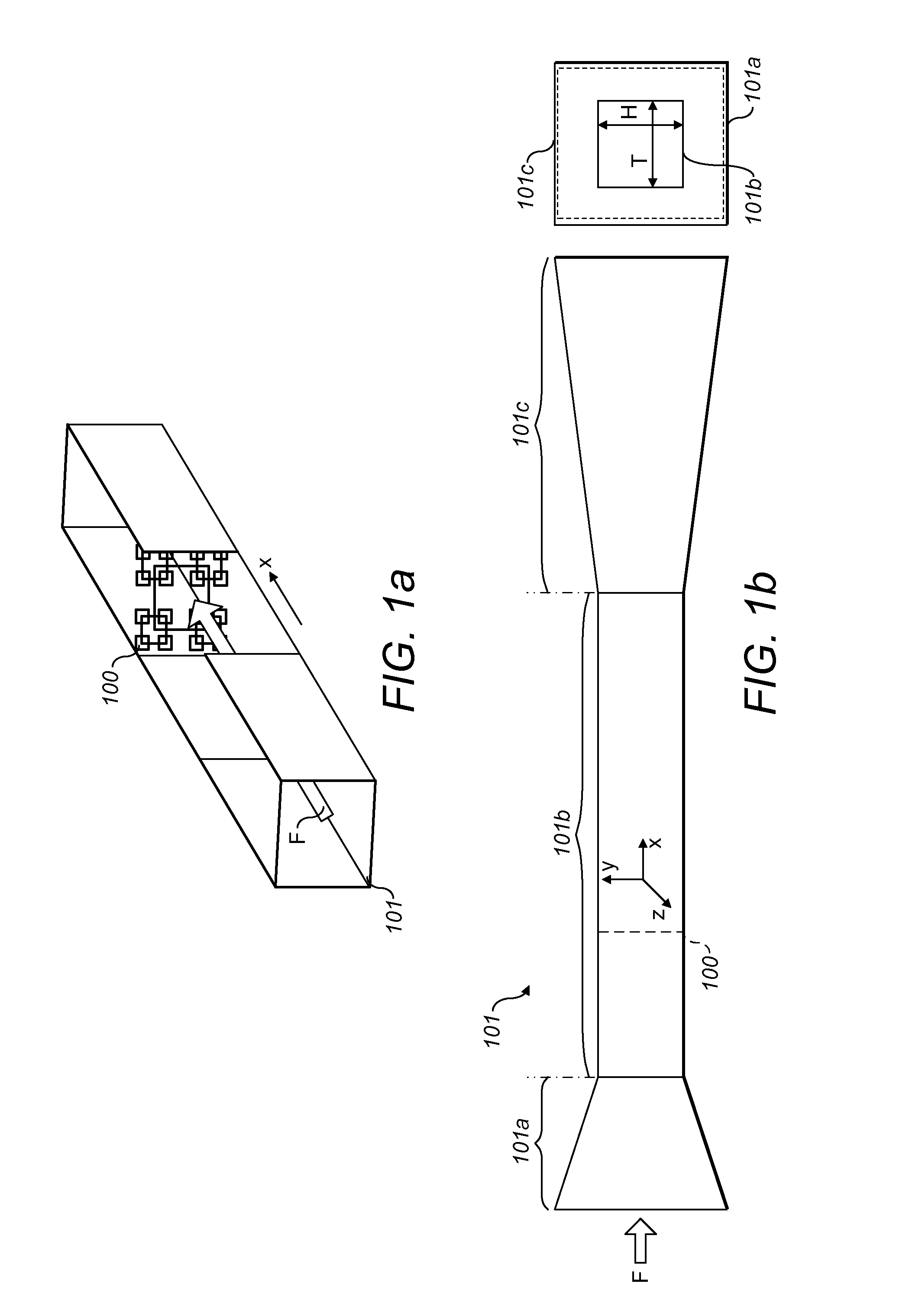
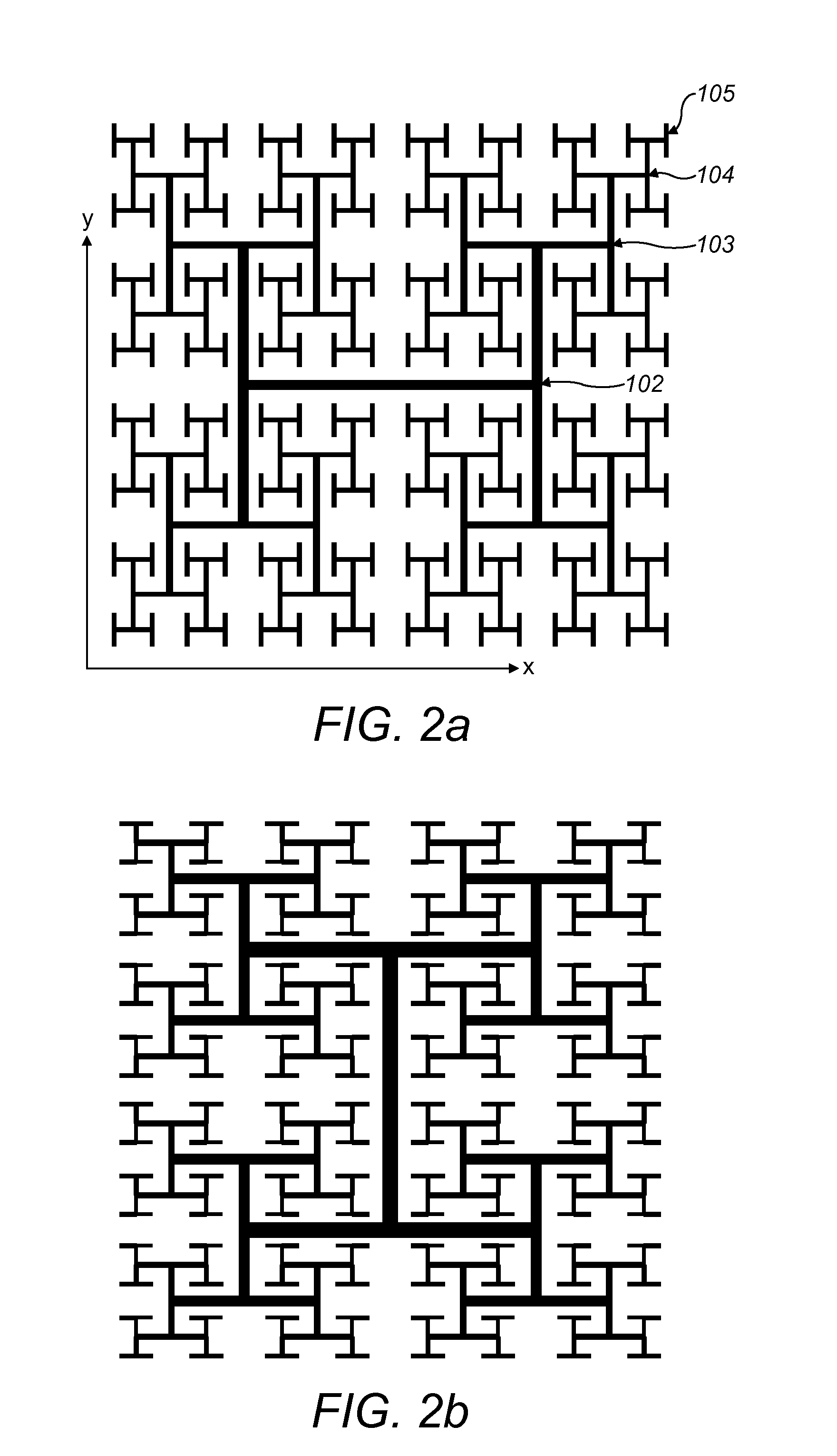
[0010]Embodiments of the invention thus incorporate one or more inserts with turbulence-creating elements arranged in a fractal configuration; in this way, exemplary such fluid flow modification apparatus are significantly less bulky and complex than known alternative mixers, whilst providing similar, if not improved, levels of mixing to those achieved by known mixing devices.
[0011]In a preferred embodiment of the invention, the insert is attachable to each of at least two turbulence-creating elements, such that the arrangement of the inserts is symmetrical about a centre point of the fluid flow field. It has been observed that the symmetrical arrangement of the inserts significantly improves mixing achieved by the fluid flow modification apparatus.
[0012]The insert is preferably made of a substantially rigid material. In a further preferred embodiment of the invention, the insert is porous or perforated. The inclusion of pores or perforations in the insert provides a greater mixing effect.
[0013]Preferably, the turbulence-creating element to which the insert is attachable is the turbulence-creating element in closest proximity to a centre point of the fluid flow field. It has been observed that the placement of an insert close to the centre point of the fluid flow field has a significant impact on the mixing capability of the insert.

Problems solved by technology

However, the SMV® gas (fluid) mixer is a relatively complex and bulky piece of apparatus that requires careful installation in a fluid flow field prior to its use.

Method used


Image

  • Fluid flow modification apparatus
  • Fluid flow modification apparatus
  • Fluid flow modification apparatus

Examples


first embodiment

[0044]FIG. 4 shows a grid 300 in accordance with the invention. The grid 300 is of a configuration similar to the conventional grids 200 shown in FIGS. 3a and 3b. However, the grid 300 additionally has a generally rectangularly-shaped insert 306 attached to a first surface portion (against which fluid flows) of each elongate member of structure 302, which is the only structure that encompasses a centre point 307 of the fluid flow field within its boundary. The arrangement of the inserts 306 in the structure 302 is such that the inserts 306 are symmetrical about the centre point 307 of the fluid flow field, the centre point 307 coinciding with a centre point of the structure 302. As can be seen in FIG. 4, the inserts 306 are of greater width than the elongate members of the structure 302, such that each insert 306 overlaps or protrudes beyond the edges of the respective elongate member that it covers. It will be noted that the inserts 306 obstruct the flow of fluid between elongate m...

second embodiment

[0051]In the embodiment of the invention shown in FIG. 7, the insert arrangement of the invention is combined with four additional substantially square-shaped inserts 512 that are arranged along an outer periphery of the inserts 506. Each insert 512 is arranged approximately at the mid-point of the insert 506 and is located on the outer periphery thereof, such that it falls within a gap between adjacent fourth-level structures 505. The arrangement of the inserts 512 is symmetrical about the centre point 507 of the fluid flow field.

[0052]FIG. 8 shows a further embodiment of the invention in which the insert arrangement of FIG. 7 is supplemented with a further set of four substantially square-shaped inserts 513 that are arranged on the inner peripheries of inserts 506. Each insert 513 is arranged at the approximate mid-point of the insert 506 on which inner periphery it is located, such that it falls within a gap between adjacent fourth-level structures 505 and is symmetrical with the...


PUM


Abstract

A fluid flow modification apparatus for creating turbulence in a moving fluid includes turbulence-creating elements arranged in a fractal configuration, each element having a first surface portion against which the fluid can flow and a second surface portion along which the fluid can flow, and further includes an insert for arrangement to obstruct the flow of fluid between adjacent second surface portions of at least two turbulence-creating elements. A support holds the turbulence-creating elements in the fluid to allow movement of the fluid relative to the turbulence-creating elements and the insert. The insert may be attachable to at least two turbulence-creating elements, such that the arrangement of the inserts is symmetrical about a centre point of the fluid flow field for improved mixing.

Description

FIELD OF THE INVENTION[0001]The present invention relates to apparatus for modifying the properties of a flow field. Embodiments of the invention can be used to control the mixing of fluids, heat, mass and momentum transfer within and between fluids, acoustic noise, oscillations in fluids, microchip cooling, structural vibrations and chemical reactions. Particular applications to which embodiments of the invention are particularly well suited include labyrinth seals, ventilation systems, combustors, chemical reactors and silent, as well as efficient brakes and airbrakes on air-, land- and seaborne vehicles and / or platforms.BACKGROUND OF THE INVENTION[0002]It is well-known that the mixing of fluids can be achieved by creating a turbulent fluid flow in a fluid flow field. One way of creating turbulent flow is to introduce a blockage into the fluid flow field. However, it is important to ensure that any blockage that causes turbulence, and therefore mixing, is not excessive. Ideally, t...

Claims


Application Information

Patent Timeline
Patent Type & Authority Applications(United States)
IPC IPC(8): B01F5/06
CPCB64C9/32B64C9/323F15D1/10F15D1/025B01F25/41B01F25/4316
Inventor VASSILICOS, JOHN CHRISTOSSEOUD, RICHARD ELIAN
Owner IMPERIAL INNOVATIONS LTD
Why Eureka
Eureka Blog
Learn More