Timepiece bearing, movement, and portable timepiece
- Summary
- Abstract
- Description
- Claims
- Application Information
AI Technical Summary
Benefits of technology
Problems solved by technology
Method used
Image
Examples
Embodiment Construction
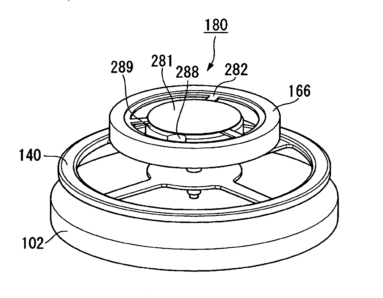
[0079]Next, a timepiece bearing according to an embodiment of the present invention will be described with reference to FIGS. 1 through 20. In this embodiment, described below, the timepiece bearing is applied to a portable mechanical timepiece such as a wristwatch.
(Mechanical Timepiece)
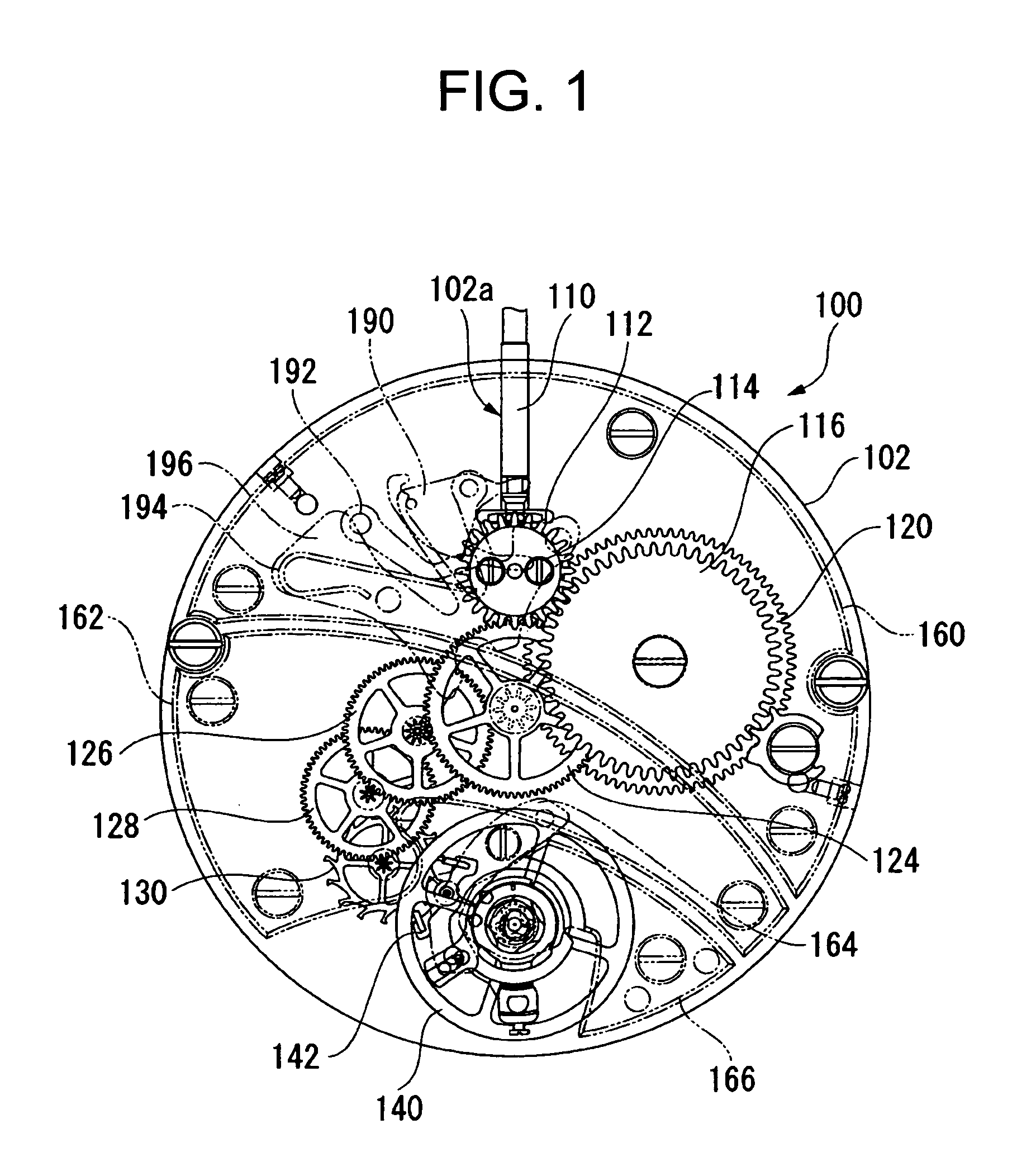
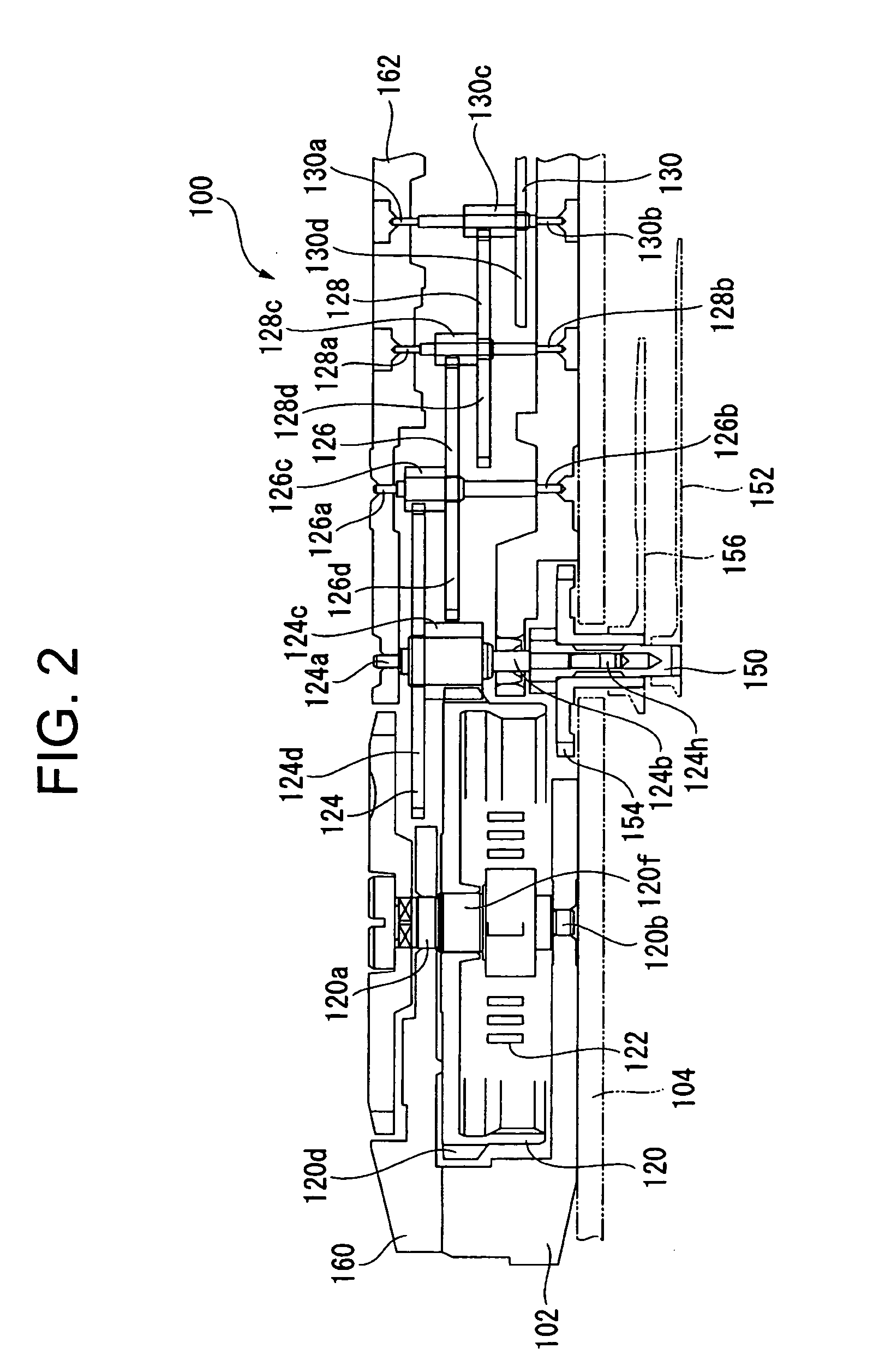
[0080]As shown in FIGS. 1 through 3, a movement 100 of a mechanical timepiece has a main plate 102 constituting a base plate of the movement 100. A winding stem 110 is rotatably incorporated into a winding stem guide hole 102a of the main plate 102. A dial 104 (See FIG. 2) is mounted to the movement 100. Generally speaking, of the two sides of the main plate 102, the side where the dial 104 is arranged is referred to as the back side of the movement 100, and the side opposite to the side where the dial 104 is arranged is referred to as the front side of the movement 100. A train wheel assembled to the front side of the movement 100 is referred to as the front train wheel, and a train wheel assembled ...
PUM
 Abstract
Description
Claims
Application Information
 - R&D
- Intellectual Property
- Life Sciences
- Materials
- Tech Scout
- Unparalleled Data Quality
- Higher Quality Content
- 60% Fewer Hallucinations
Browse by: Latest US Patents, China's latest patents, Technical Efficacy Thesaurus, Application Domain, Technology Topic, Popular Technical Reports.
© 2025 PatSnap. All rights reserved.Legal|Privacy policy|Modern Slavery Act Transparency Statement|Sitemap|About US| Contact US: help@patsnap.com


