Fiber Optic Connector Assembly and Methods Therefor

a fiber optic connector and connector technology, applied in the field of fiber optic connector assembly, can solve the problems of difficult installation and removal of such dedicated pairs

Inactive Publication Date: 2011-04-07
CORNING CABLE SYST LLC
View PDF9 Cites 44 Cited by
  • Summary
  • Abstract
  • Description
  • Claims
  • Application Information

AI Technical Summary

Benefits of technology

A fiber optic connector assembly includes at least one fiber optic cable and at least one connector attached to the at least one fiber optic cable. The connector includes a housing and a boot attached to the housing and about the at least one fiber optic cable, and a cli

Problems solved by technology

However, high density environments make install

Method used


Image

  • Fiber Optic Connector Assembly and Methods Therefor
  • Fiber Optic Connector Assembly and Methods Therefor
  • Fiber Optic Connector Assembly and Methods Therefor

Examples


Embodiment Construction

Reference is now made in detail to the present preferred embodiments of the disclosure, examples of which are illustrated in the accompanying drawings. Whenever possible, identical or similar reference numerals are used throughout the drawings to refer to identical or similar parts. It should be understood that the embodiments disclosed herein are merely examples with each one incorporating certain benefits of the present disclosure. Various modifications and alterations may be made to the following examples within the scope of the present disclosure, and aspects of the different examples may be mixed in different ways to achieve yet further examples. Accordingly, the true scope of the disclosure is to be understood from the entirety of the present disclosure in view of, but not limited to the embodiments described herein.

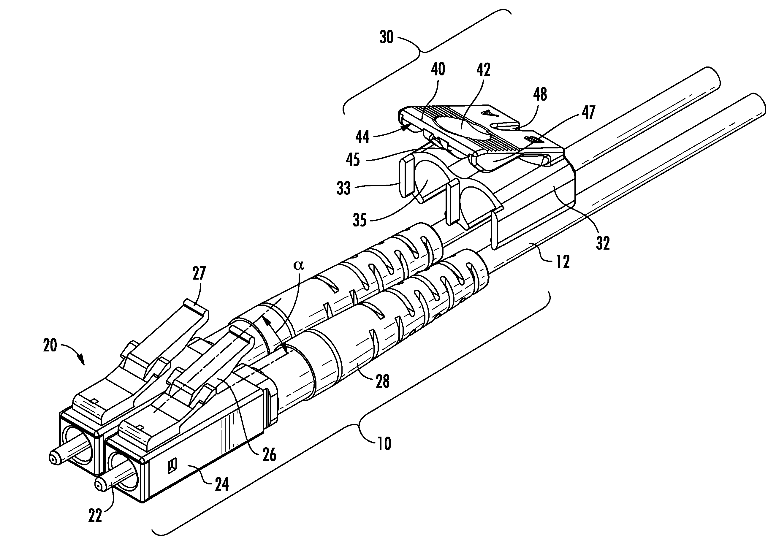
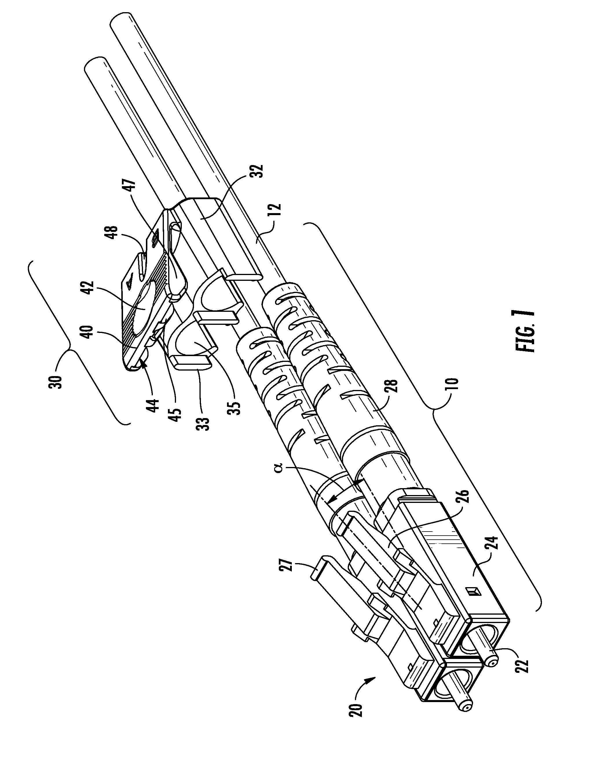
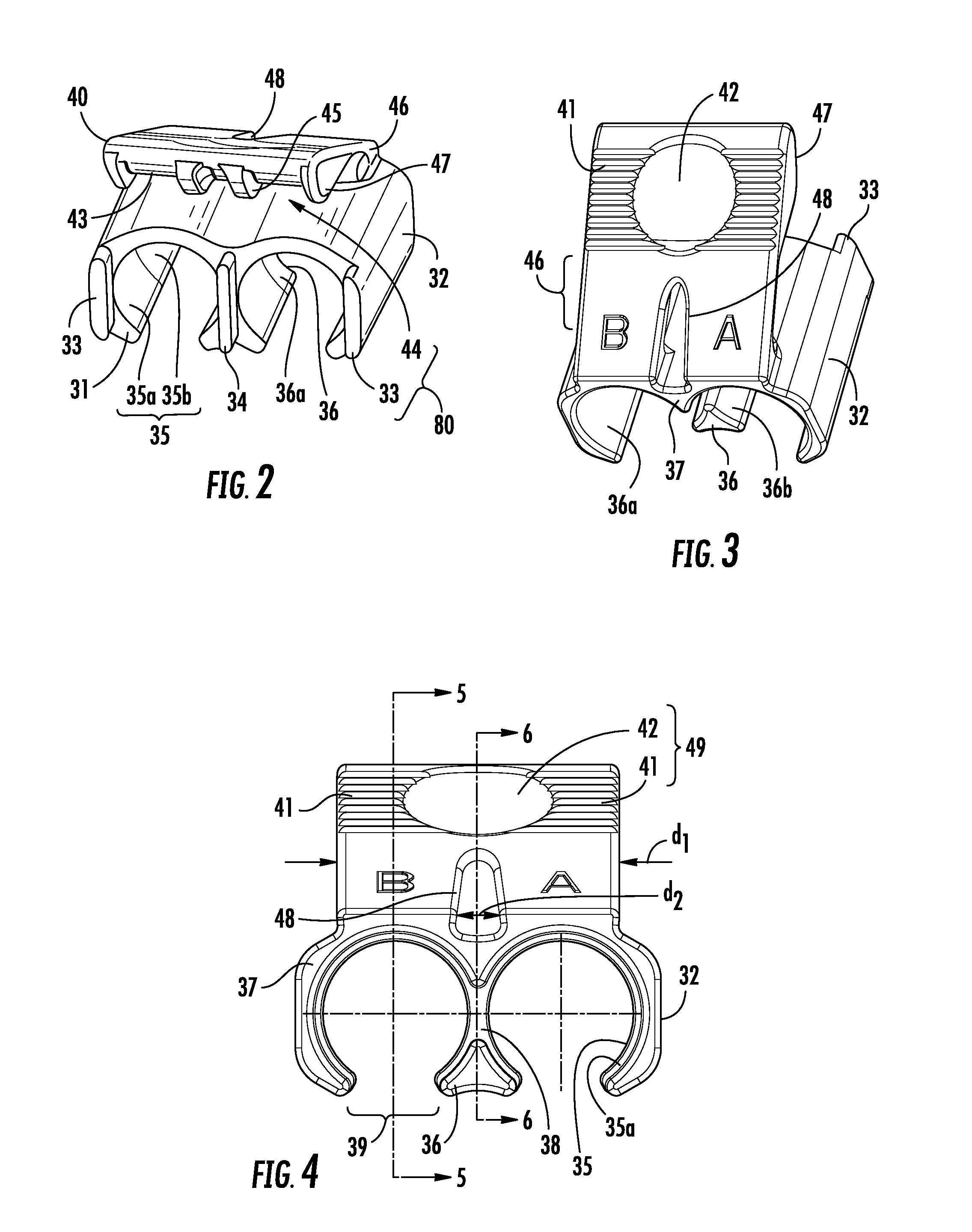
A multi-connector assembly, for example, a duplex fiber optic connector assembly, is disclosed having two fiber optic connectors on a fiber optic cable joined toge...


PUM


Abstract

A fiber optic connector assembly includes two connectors on fiber optic cables joined together by a clip having a trigger arm and a clip body. The trigger arm extends from the clip body at a shallow angle. The shallow angle of the trigger arm effectively reduces an amount of normal force required to activate latch mechanisms on the connectors. The clip is sandwiched between a connector housing and a boot, inhibiting the clip from axially translating relative to the connector assembly. The clip further includes an anti-rotation system to inhibit rotation of the connector assembly relative to the clip.

Description

BACKGROUND1. Technical FieldA fiber optic connector assembly is disclosed and methods therefor. In particular, a fiber optic clip is disclosed that combines two fiber optic connectors on fiber optic cable into a duplex fiber optic connector assembly and methods therefor.2. Technical BackgroundFiber optic networks typically use dedicated input and output channels, usually called ports, each input and output channel having a single optical fiber in a connector assembly. High density environments require that many ports be arranged into arrays, usually in rack mounted hardware. For better organization, input and output channels are grouped together in pairs with one pair representing one port. However, high density environments make installing and removing such dedicated pairs difficult. What is needed is a clip that secures pairs of connectors together and maintains predetermined lateral and axial alignment for the dedicated pairs while easing installation and removal tasks.SUMMARYA f...

Claims


Application Information

Patent Timeline
IPC IPC(8): G02B6/38
CPCG02B6/3879
Inventor JONES, ASHLEY W.
Owner CORNING CABLE SYST LLC
Why Eureka
Try Eureka