Mobile communication system, mobile communication device, and mobile communication method

a mobile communication system and mobile communication technology, applied in wireless communication, wireless communication, wireless communication, etc., can solve the problems of rayleigh fading and the difficulty of mobile communication devices performing demodulation processes, and achieve the effect of preventing the degradation of communication quality

Inactive Publication Date: 2011-04-07
SHARP KK
View PDF1 Cites 20 Cited by
  • Summary
  • Abstract
  • Description
  • Claims
  • Application Information

AI Technical Summary

Benefits of technology

[0026]According to the present invention, the mobile communication device transmits the reference signal from the transmission antenna in the resource block being assigned for data transmission. The mobile communication device transmits the reference signal from another antenna other than the transmission antenna in the resource block that is not being assigned for data transmission. For this reason, a proper AMC control can be achieved based on the reference signal transmitted from the transmission antenna without the inconvenience of not being able to optimally switch the transmission antenna. Therefore, such a control can achieve the effect of preventing degradation of the communication quality.

Problems solved by technology

When a mobile communication device receives a transmission signal from a base station device, a variation in relative positions of the base station device and the mobile communication device causes Rayleigh fading.
If the signal amplitude greatly decreases upon the reception causing such a variation, the characteristics of reception signals greatly degrade, thereby making it difficult for the mobile communication device to perform a demodulation process.

Method used


Image

  • Mobile communication system, mobile communication device, and mobile communication method
  • Mobile communication system, mobile communication device, and mobile communication method
  • Mobile communication system, mobile communication device, and mobile communication method

Examples


Embodiment Construction

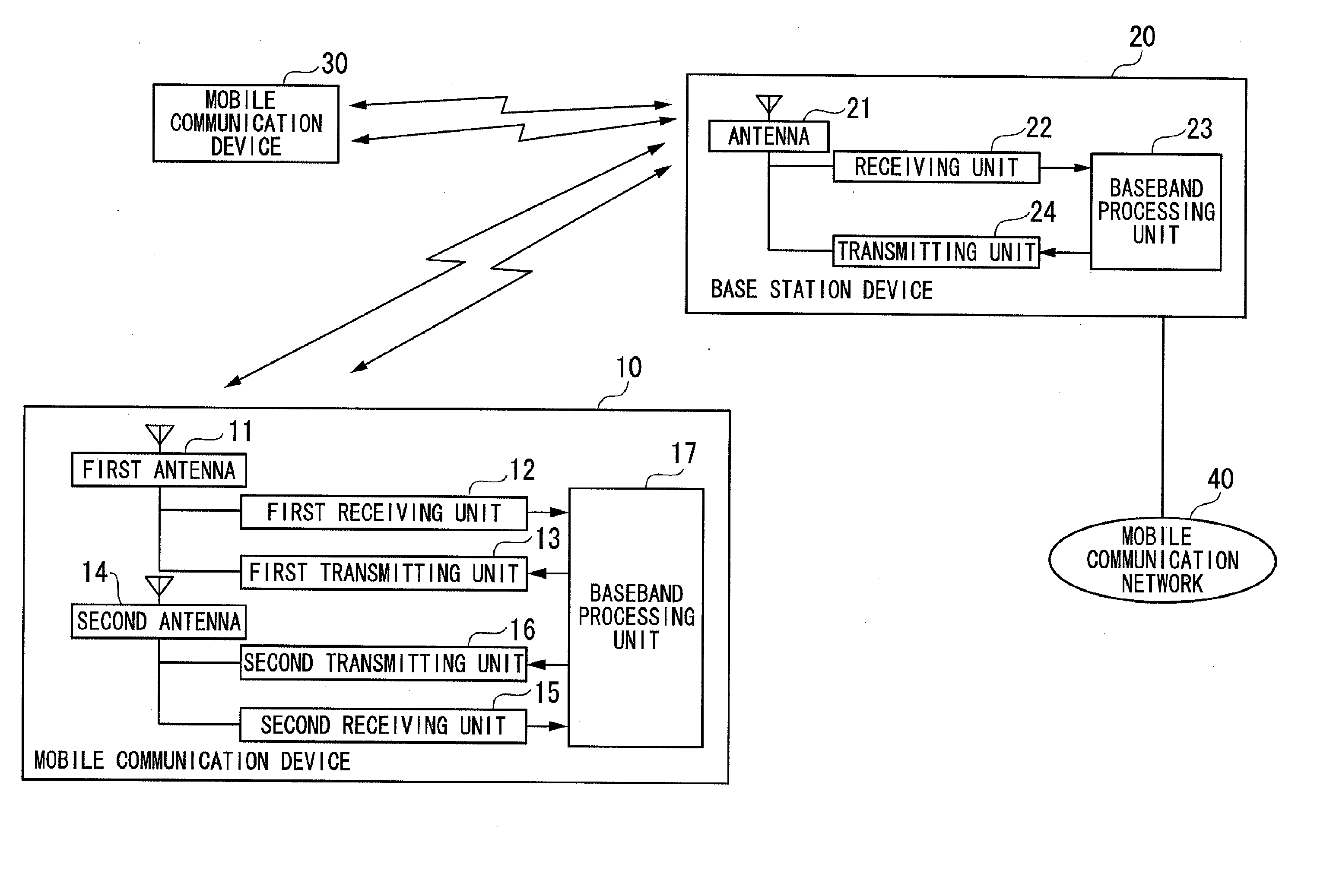
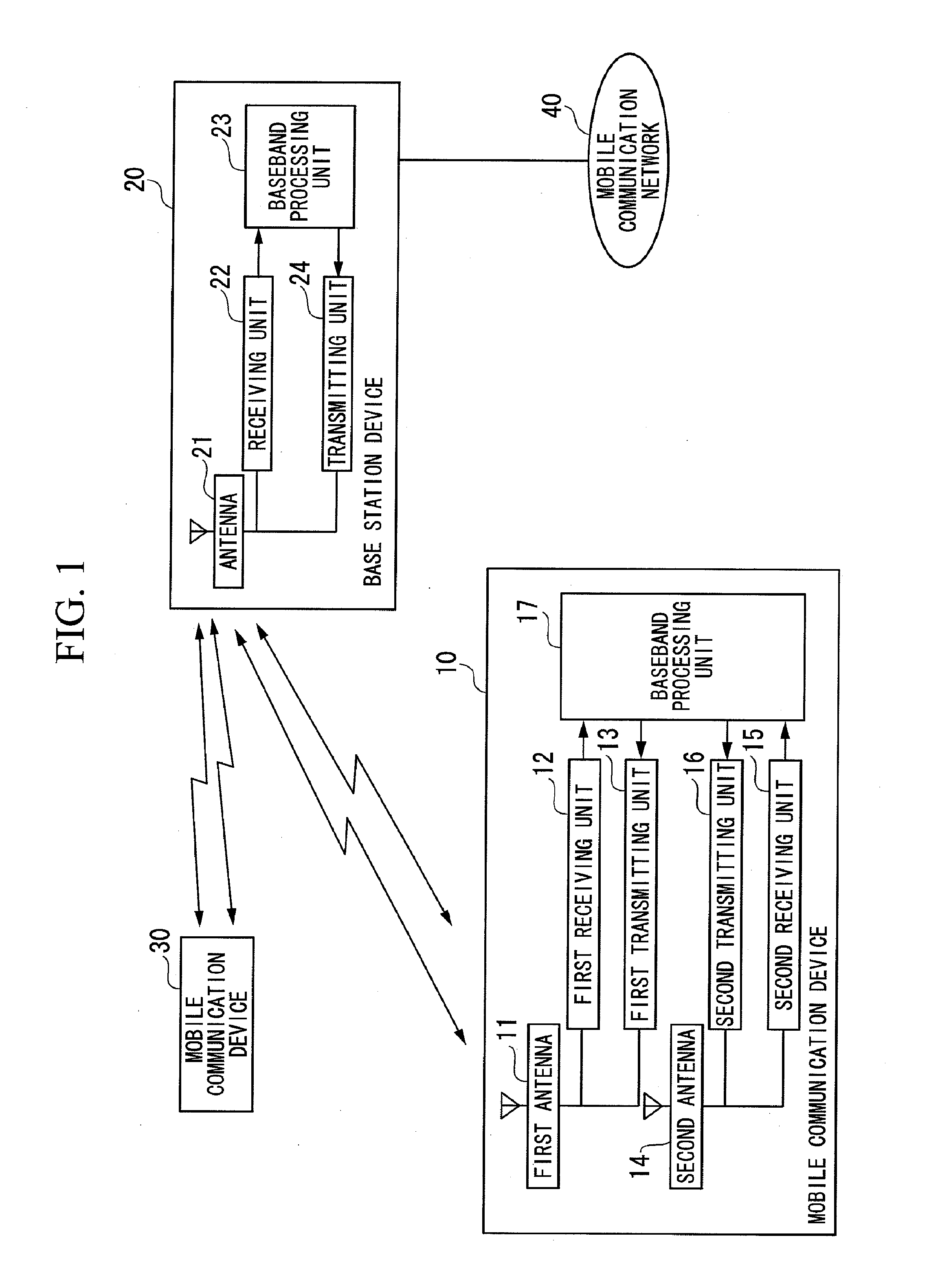
[0031]Hereinafter, a mobile communication device according to a first embodiment of the present invention is explained with reference to the accompanying drawings. FIG. 1 is a block diagram illustrating a network configuration of the entire mobile communication system according to the first embodiment. The mobile communication system shown in FIG. 1 includes: mobile communication devices 10 and 30 including multiple antennas; and a base station device 20. The base station device 20 is connected to a mobile communication network 40. The mobile communication device 10 performs wireless communication with the base station device 20. The mobile communication device 10 performs wireless communication with the other mobile communication device 30 through the base station device 20 or through the base station device 20 and the mobile communication network 40. The mobile communication device 10 includes a transmission antenna and an idle antenna. The mobile communication device 10 transmits...


PUM


Abstract

A mobile communication device includes antennas, transmitting units, and receiving units. A baseband processing unit of the mobile communication device transmits data signals to a base station device through a receiving unit and an antenna that are selected based on an instruction received from the base station device. The baseband processing unit transmits reference signals to the base station device through the transmitting units and the antennas while preventing transmission frequencies of the reference signals from overlapping one another. A baseband processing unit of the base station device transmits, to the mobile communication device based on qualities of the received reference signals, a signal indicating information concerning which of the antennas and the transmitting units of the mobile communication device are used for transmitting the data signals, the signal also indicating information concerning whether or not to make the transmitting units and the antennas share transmission of the reference signals. Thus, interferences due to degradation of communication quality and to an increase in the number of reference signals can be prevented.

Description

TECHNICAL FIELD[0001]The present invention relates to a mobile communication system, a mobile communication device, and a mobile communication method.[0002]Priority is claimed on Japanese Patent Application No. 2008-149885, filed Jun. 6, 2008, the content of which is incorporated herein by reference.BACKGROUND ART[0003]When a mobile communication device receives a transmission signal from a base station device, a variation in relative positions of the base station device and the mobile communication device causes Rayleigh fading. The Rayleigh fading causes a great variation in the phase and amplitude of reception signals. If the signal amplitude greatly decreases upon the reception causing such a variation, the characteristics of reception signals greatly degrade, thereby making it difficult for the mobile communication device to perform a demodulation process. Such a phenomenon might occur similarly in a reverse link, i.e., when the base station device receives signals transmitted ...

Claims


Application Information

Patent Timeline
Patent Type & Authority Applications(United States)
IPC IPC(8): H04B7/00
CPCH04B7/04H04W28/04H04W48/08H04W88/08H04W72/0406H04W88/06H04W48/18H04W72/20
Inventor SHIMONABE, TADASHIOHSHIMA, AKIRASAKAMOTO, MITSURUTAKAGI, YUHSUKE
Owner SHARP KK
Why Eureka
Try Eureka