Bulk acoustic wave resonator and method of fabricating same

Active Publication Date: 2011-04-14
AVAGO TECH INT SALES PTE LTD
View PDF23 Cites 88 Cited by
  • Summary
  • Abstract
  • Description
  • Claims
  • Application Information

AI Technical Summary

Problems solved by technology

When the PZ layer is deposited, it follows the terrain of the underlayer and has a tendency to crack when layered over sharp topography, for example, on electrode layer that has a nearly vertical edge making an abrupt end.
Cracks in the PZ layer significantly decrease the ESD robustness of resonator.
However, the voids or cracks in PZ layer when deposited over the edge of its underlying electrode 94 lead to serious

Method used


Image

  • Bulk acoustic wave resonator and method of fabricating same
  • Bulk acoustic wave resonator and method of fabricating same
  • Bulk acoustic wave resonator and method of fabricating same

Examples


first embodiment

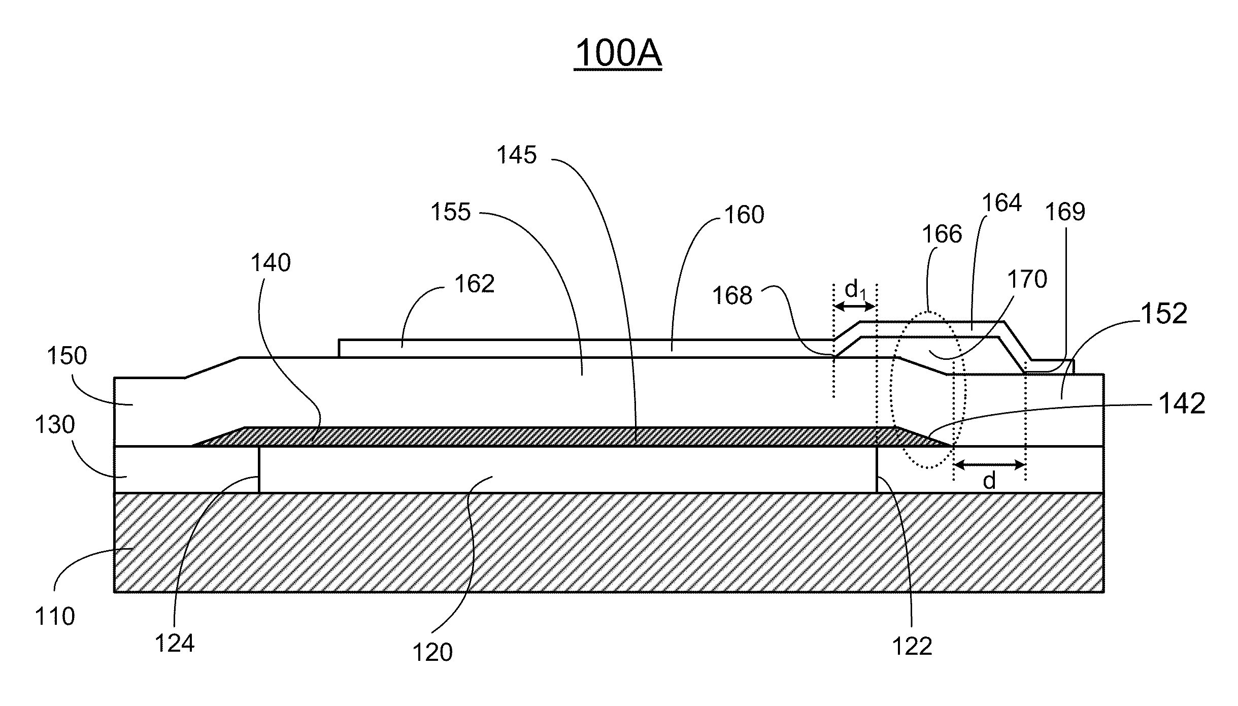
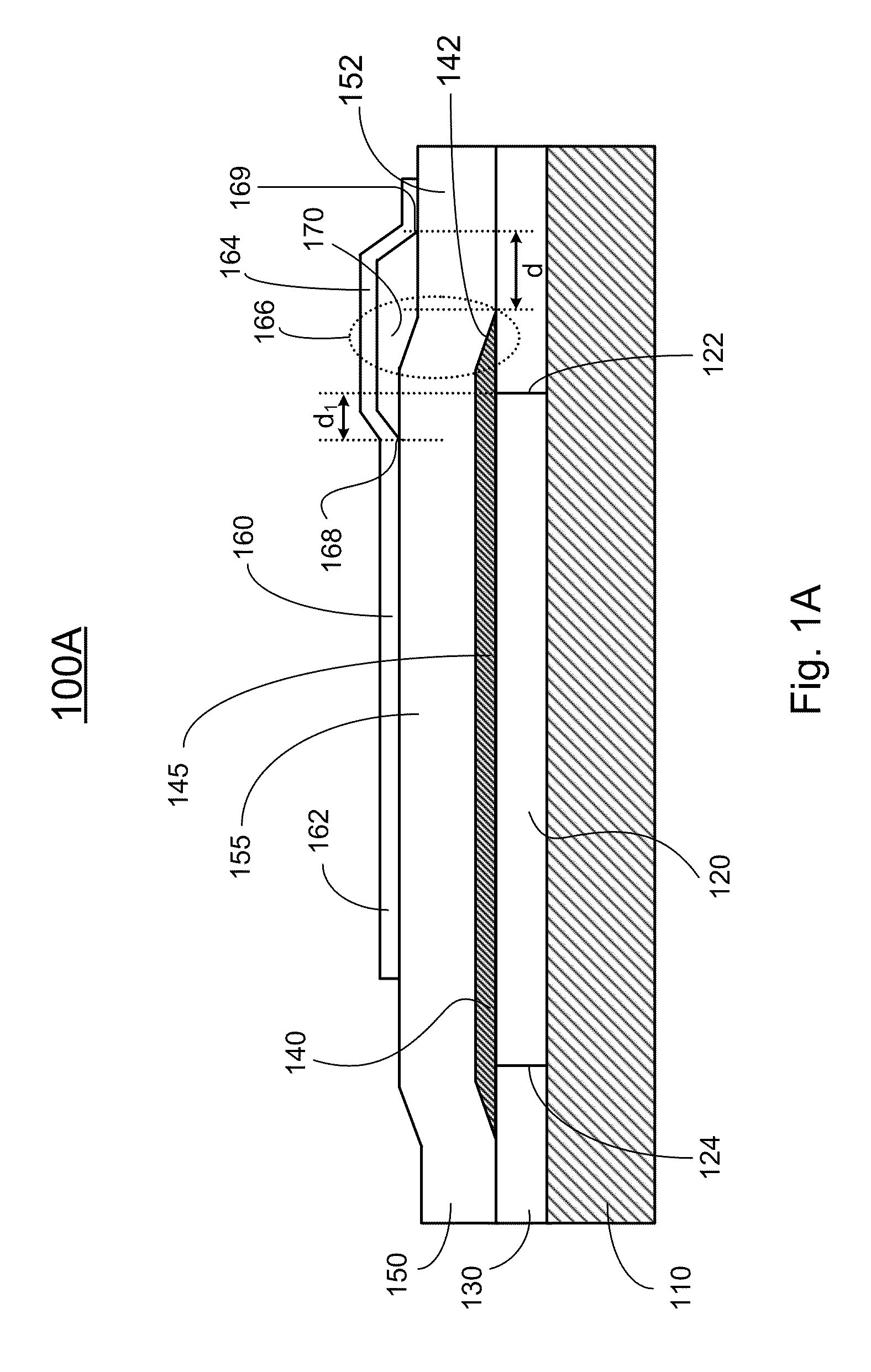
[0054]Referring now to FIG. 1A, a BAW resonator 100A is shown according to the present invention. The BAW resonator 100 includes a substrate 110 and an acoustic mirror 120 that is formed on a top surface of the substrate 110 or in the substrate 110. Although the acoustic mirror 120 as shown in FIG. 1A is provided by an air cavity 120 defined between the substrate 110 and the dielectric layer 130 deposited on the top surface of the substrate 110, it would be appreciated that any other acoustic mirror structure such as a Bragg reflector is also applicable.

[0055]The BAW resonator 100A also includes a first electrode 140, a piezoelectric layer 150 and a second electrode 160. The first electrode 140 is deposited on the top surface of the dielectric layer 130 and overlapping the acoustic mirror 120. The first electrode 140 may be etched to form a tapered end portion 142, which extends beyond the contour / edge 122 of the acoustic mirror 120. Additionally, the first electrode 140 may be form...

second embodiment

[0059]Referring to FIG. 2A, a BAW resonator 200A is shown according to the present invention. The BAW resonator 200A comprises a substrate 210, an acoustic mirror 220 formed in or on the substrate 210, having a first edge 222 and an opposite, second edge 224, a dielectric layer 230 formed on the substrate 210 such that the dielectric layer 230 is substantially in contact with the first and second edges of the acoustic mirror 220, a first electrode 240 formed on the acoustic mirror 220, having a first end portion 242 and an opposite, second end portion defining a body portion therebetween, where the first end portion 242 is located between the first edge 222 and the second edge 224 of the acoustic mirror 220, a piezoelectric layer 250 formed on the first electrode 240, having a body portion 255, a first end portion 252 and a second end portion oppositely extending from the body portion onto the dielectric layer 230; and a second electrode 260 formed on the piezoelectric layer 250, ha...

fourth embodiment

[0067]Referring now to FIG. 4, a BAW resonator 400 is shown according to the present invention. The BAW resonator 400 comprises a substrate 410 having an acoustic mirror 420 in or on a top surface thereof. While the acoustic mirror 420 as shown in FIG. 4 is provided by an air cavity 420 in the dielectric layer 430 deposited on the top surface of the substrate 410, any other acoustic mirror structure such as a Bragg reflector is also applicable. A first electrode 440 is deposited on the dielectric layer 430 and over the acoustic mirror 420, and the first electrode 440 is etched forming a tapered end portion 442. Additionally, an tapered end portion edge 448 of the first electrode 440 terminates within the contour 422 of the acoustic mirror 420, i.e., there is a distance (d3) between the tapered end portion edge 448 of the first electrode and the corresponding contour 422 of the acoustic mirror 420.

[0068]A piezoelectric layer 450 is deposited on the first electrode 440. The piezoelect...


PUM

PropertyMeasurementUnit
Dielectric polarization enthalpyaaaaaaaaaa
Shapeaaaaaaaaaa
Areaaaaaaaaaaa

Abstract

An acoustic resonator with improved quality factor and electro-mechanical coupling is disclosed. In one embodiment, the acoustic resonator includes an acoustic mirror formed on the top surface of a substrate or in the substrate, a first electrode having a end portion, formed on the acoustic mirror, a piezoelectric layer formed on the first electrode; and a second electrode formed on the piezoelectric layer, where at least one of the first electrode and the second electrode and the piezoelectric layer define an air gap in a region that overlaps the end portion of the first electrode. In one embodiment, a dielectric film is deposited on the surface of the end portion of the first electrode to form completely planarized surface before the piezoelectric layer deposition. In another embodiment, an air gap between the second electrode and the piezoelectric layer, so that the piezoelectric coupling in the end portion area of the first electrode is minimally contributed into the whole resonator.

Description

CROSS-REFERENCE TO RELATED PATENT APPLICATION[0001]Some references, which may include patents, patent applications and various publications, are cited and discussed in the description of this invention. The citation and / or discussion of such references is provided merely to clarify the description of the present invention and is not an admission that any such reference is “prior art” to the invention described herein. All references cited and discussed in this specification are incorporated herein by reference in their entireties and to the same extent as if each reference were individually incorporated by reference.FIELD OF THE INVENTION[0002]The present invention relates generally to piezoelectric thin film devices, and more particular to bulk acoustic wave resonators having enhanced performance and methods of manufacturing same.BACKGROUND OF THE INVENTION[0003]Thin film Bulk Acoustic Wave (BAW) resonators utilizing the thickness longitudinal resonance of a piezoelectric (PZ) film...

Claims


Application Information

Patent Timeline
IPC IPC(8): H03H9/54B05D5/12
CPCH03H3/04H03H9/132H03H9/173H03H9/175H03H9/584H03H9/587Y10T29/42H03H3/02H03H9/02086H03H9/177H03H9/566Y10T29/49005H03H9/589
Inventor ZHANG, HAO
Owner AVAGO TECH INT SALES PTE LTD
Why Eureka
Try Eureka