Bulk acoustic wave resonator with rough surface, filter, and electronic device

A bulk acoustic wave resonator and rough surface technology, applied in the field of acoustic wave resonators, can solve problems such as the decrease of electromechanical coupling coefficient

Pending Publication Date: 2020-05-22
TIANJIN UNIV +1
View PDF12 Cites 7 Cited by
  • Summary
  • Abstract
  • Description
  • Claims
  • Application Information

AI Technical Summary

Problems solved by technology

[0009] In order to alleviate or solve the rough structure in the FBAR, the electromechanical coupling coefficient of the resonator is Kt 2

Method used


Image

  • Bulk acoustic wave resonator with rough surface, filter, and electronic device
  • Bulk acoustic wave resonator with rough surface, filter, and electronic device
  • Bulk acoustic wave resonator with rough surface, filter, and electronic device

Examples


Embodiment Construction

[0043] The technical solutions of the present invention will be further specifically described below through the embodiments and in conjunction with the accompanying drawings. In the specification, the same or similar reference numerals designate the same or similar components. The following description of the embodiments of the present invention with reference to the accompanying drawings is intended to explain the general inventive concept of the present invention, but should not be construed as a limitation of the present invention.

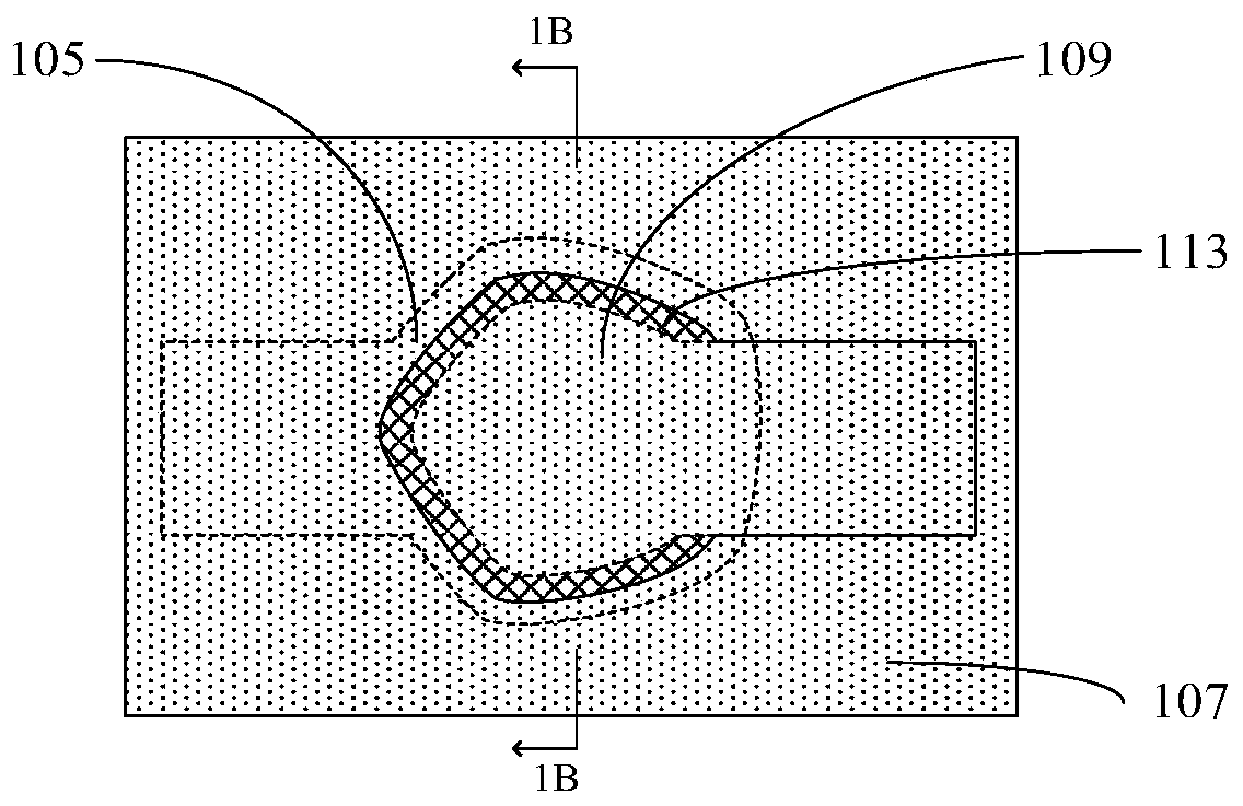
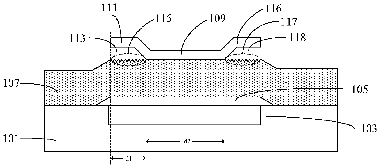
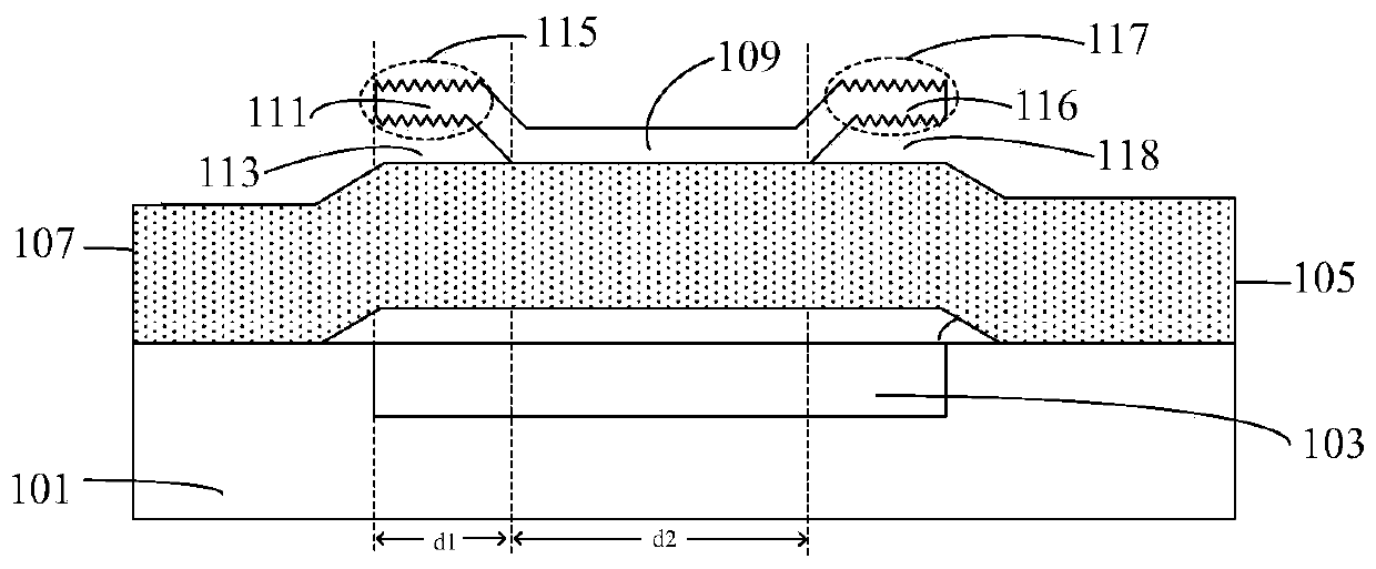
[0044] In the present invention, a bridge wing or bridge portion structure containing roughness is processed at one side or multiple edges of the electrode of the resonator. The bridge wing or bridge portion structure can effectively reduce the influence of the lateral spurious mode on the performance of the resonator, and effectively improve its performance. Q value.

[0045] Refer to the attached Figure 1-4 A bulk acoustic wave resonator ...


PUM


Abstract

The present invention relates to a bulk acoustic wave resonator, and the resonator comprises a substrate; an acoustic mirror; a bottom electrode disposed over the substrate; a top electrode opposed tothe bottom electrode; and a piezoelectric layer which is arranged above the bottom electrode and between the bottom electrode and the top electrode, wherein the overlapped area of the acoustic mirror, the bottom electrode, the piezoelectric layer and the top electrode in the thickness direction of the substrate is the effective area of the resonator; the resonator is adjacent to the boundary of the effective area, and an air gap is formed outside the boundary; at least one surface in the surfaces corresponding to the air gaps is a rough surface, and the roughness of the rough surface is greater than that of part of the surface around the rough surface of the part where the rough surface is located; and rare earth elements are doped in the piezoelectric layer. The invention further relatesto a filter with the resonator and electronic equipment with the filter.

Description

technical field [0001] Embodiments of the present invention relate to an acoustic wave resonator, in particular to a bulk acoustic wave resonator, a filter with the resonator, and an electronic device with the filter. Background technique [0002] With the rapid development of wireless communication technology, there is an increasing demand for multi-passband transceivers that can simultaneously process large amounts of data. In recent years, multi-passband transceivers have been widely used in positioning systems and multi-standard systems. These systems need to process signals of different frequency bands simultaneously to improve the overall performance of the system. Although the number of frequency bands in a single chip continues to increase, consumers are increasingly demanding miniaturized, multi-functional portable devices, and miniaturization has become the development trend of chips, which puts higher demands on the size of filters. requirements. [0003] For th...

Claims


Application Information

Patent Timeline
IPC IPC(8): H03H9/02H03H9/05H03H9/17
CPCH03H9/02015H03H9/02047H03H9/0504H03H9/171H03H9/05H03H9/17H03H9/02H03H9/54H03H3/02
Inventor 张孟伦庞慰刘伯华杨清瑞
Owner TIANJIN UNIV
Why Eureka
Try Eureka