Phosphor and manufacturing method for the same, and light source

a manufacturing method and phosphor technology, applied in the field of phosphor and manufacturing methods for the same, and light sources, can solve the problems of short life span, insufficient emission in the longer wavelength side of the visible light region, violent heat generation, etc., and achieve the effect of improving emission efficiency, improving efficiency, and improving emission efficiency

Active Publication Date: 2006-03-30
CITIZEN ELECTRONICS CO LTD +1
View PDF48 Cites 83 Cited by
  • Summary
  • Abstract
  • Description
  • Claims
  • Application Information

AI Technical Summary

Benefits of technology

[0055] The phosphor according to any one of the eighth aspect to tenth aspect is in a powdery state, and therefore coating and filling of the phosphor can be easily performed. Further, since the average particle size of the phosphor powder is not more than 20 μm and not less than 0.1 μm, and the specific surface area is not more than 50 m2 / g and not less than 0.1 m2 / g, the emission efficiency can be improved.
[0056] According to the manufacturing method of the phosphor of any one of the eleventh to twenty-second aspects, by adding the boron compound such as BN and H3BO3 as an additive agent other than the raw material of the phosphor, the producing temperature of the liquid phase generated in the process of the solid phase reaction is decreased, and the phosphor having an improved emission efficiency can be manufactured.
[0057] Also, by adding the fluorine compound such as CaF2 and AlF3 as the additive agent other than the raw material of the phosphor, the producing temperature of the liquid phase generated in the process of the solid phase reaction can be decreased, and the phosphor having the improved efficiency can be manufactured.
[0058] According to the manufacturing method of the phosphor of the fifteenth aspect, by using AlN and Si3N4 with average particle size (D50) from 0.1 μm to 10.0 μm, the phosphor with particle size suitable for coating and filling, and further suitable for improving the emission intensity can be manufactured.
[0059] According to the manufacturing method of the phosphor of the twentieth aspect, the phosphor capable of suppressing adsorption of the oxygen during firing and decreasing the oxygen concentration of the phosphor and having suitable particle size for improving the emission intensity can be manufactured.
[0060] The light source according to any one of the twenty-third to twenty-fifth aspects emits light, having the excitation band in a predetermined broad wavelength range (250 nm to 550 nm) of the light emitted from the light emitting part (corresponding to LED according to the twenty-fifth aspect). Therefore, by combining the aforementioned phosphors and the light emitting part, the light source with high emission efficiency emitting the visible light or the white light can be obtained.

Problems solved by technology

Conventionally, a discharge type fluorescent lamp and an incandescent bulb used as an illumination device involve problems that a harmful substance such as mercury is contained, life span is short, and heat generation is violent.
However, in the former white LED illumination formed by combining the high luminance blue LED and the yellow phosphor (YAG:Ce), the light emission in the longer wavelength side of a visible light region is insufficient, resulting in a bluish white light emission.
Then, a red emission spectrum in the vicinity of the wavelength range from 600 nm to 700 nm is insufficient, thereby making it impossible to obtain a slightly reddish white light emission like a lamp bulb, to pose a problem of deteriorated color rendering properties.
Further, in regards to an excitation range of the yellow phosphor YAG:Ce, although having an excitation band with highest efficiency in the vicinity of 460 nm wavelength, the yellow phosphor YAG:Ce does not have the excitation band with excellent efficiency in a broad range.
Therefore, by the variation in emission wavelength due to the variation in the light emitting element during manufacturing the blue LED, the emission wavelength of the blue LED is deviated from an optimal excitation range of the YAG:Ce-based yellow phosphor, resulting in a situation of losing a wavelength balance of blue color and yellow color.
When such a situation occurs, there is the problem that the color tone of the white light obtained by synthesizing the blue light and the yellow light is changed.
This causes an insufficient mixing ratio of the phosphor such as the green phosphor improving the luminance, and the white color with high luminance can not be obtained.
Further, the red phosphor according to the conventional technique has a sharp emission spectrum, thereby involving the problem that the color rendering properties of the white light obtained is unsatisfactory.
However, although the phosphor proposed by the inventors of the present invention is improved in the point of having the emission spectrum with a broad peak in the range from yellow color to red color (580 nm to 680 nm) and an excellent excitation band in the longer wavelength side in the range from a near ultraviolet / ultraviolet as an excitation light to a visible light (250 nm to 550 nm), the problem is involved therein such that the emission intensity is not a satisfactory level.
Therefore, even when the white LED illumination is manufactured by combining the near ultraviolet / ultraviolet LED and the blue LED, the mixing ratio of only red phosphor must be increased, thereby making the green phosphor or the like insufficient to improve the luminance, and in some cases, a high luminance white color can not be obtained.
Therefore, the inventors of the present invention prepare samples of various phosphors, while pursuing the cause of not obtaining a sufficient emission intensity in the phosphor, and come to an understanding that a melting point of the raw material to be used is high, thereby making it difficult to progress a solid reaction, resulting in a non-uniform reaction.

Method used


Image

  • Phosphor and manufacturing method for the same, and light source
  • Phosphor and manufacturing method for the same, and light source
  • Phosphor and manufacturing method for the same, and light source

Examples


example

Comparative Example 1

[0118] As a comparative example 1, commercially available Ca3N2(2N), AlN(3N and having the average particle size of 1.76 μm), Si3N4(3N and having the average particle size of 0.774 μm), and Eu2O3 (3N) were prepared, and each raw material was weighed to obtain 0.985 / 3 mol of Ca3N2, 1 mol of AlN, 1 / 3 mol of Si3N4, and 0.015 / 2 mol of Eu2O3, and the raw materials thus weighed were placed in the glove-box under the nitrogen atmosphere and mixed by using the mortar. The raw materials thus mixed were put in a Si3N4 crucible, and retained / fired for 3 hours at 1500° C. in the nitrogen atmosphere, with pressure in the furnace set at 0.5 kgf / cm . Thereafter, the temperature was cooled from 1500° C. to 200° C. for 1 hour. Then, the raw materials were pulverized after firing, and the phosphor expressed by the composition formula Ca0.985AlSiN3:Eu0.015 was obtained. Note that this composition formula is estimated from the raw material used and the blending ratio.

[0119] The p...

examples 1 to 4

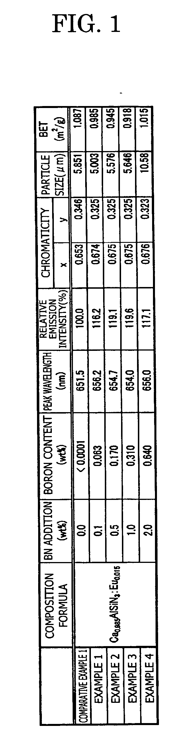
[0121] In the examples 1 to 4, the phosphor sample is manufactured in the same way as the comparative example 1, excepting that the boron nitride BN (3N) is added as the additive agent other than each raw material of Ca3N2(2N), AlN(3N), Si3N4(3N), and Eu2O3(3N), and the crucible is changed from the Si3N4 crucible to a BN crucible.

[0122] Specifically, in the example 1, 0.1 wt % of BN powder is added in a mixed raw material (before firing) of Ca0.985AlSiN3:Eu0.015. Similarly, 0.5 wt % of the BN powder is added in the example 2, 1.0 wt % of the BN powder is added in the example 3, and 2.0 wt % of the BN powder is added in the example 4, respectively.

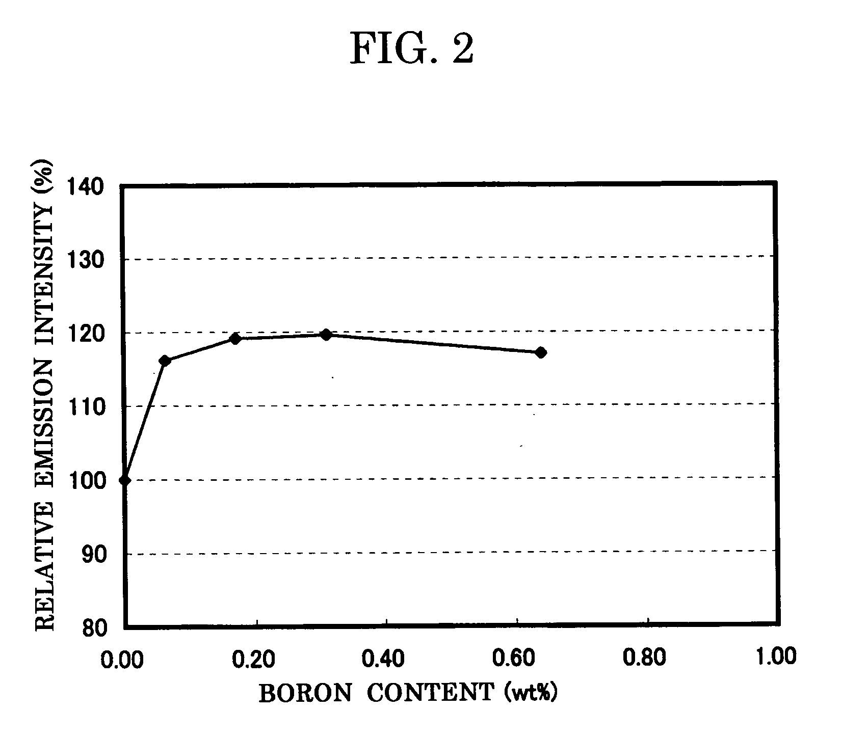
[0123] In the examples 1 to 4 also, in the same way as the comparative example 1, the composition formula of the phosphor, the analysis result of the boron concentration, and the measurement result of the emission characteristics (peak wavelength, emission intensity, and chromaticity) and the powder characteristics (particle size and spec...

examples 5 to 7

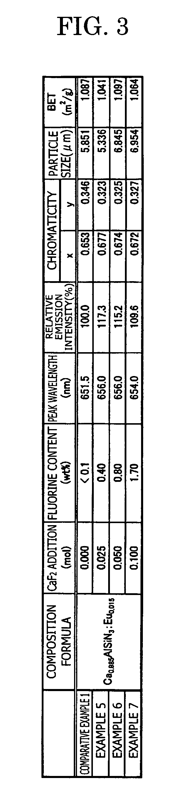
[0126] In the examples 5 to 7, in the same way as the comparative example 1, the phosphor sample is manufactured by adding fluorine calcium CaF2(3N) as an additive agent, in addition to each raw material of Ca3N2(2N), AlN(3N), Si3N4(3N), EU2O3(3N) explained in the comparative example 1, and further by changing the crucible from the Si3N4 crucible to the BN crucible.

[0127] Specifically, in the example 5, 0.025 mol of CaF2 is added to the raw material, with which 1.0 mol of Ca0.985AlSiN3:Eu0.015 is obtained. In the same way, 0.050 mol of CaF2 is added in the example 6, and 0.100 mol of CaF2 is added in the example 7.

[0128] In the comparative example 1 and the examples 5 to 7, the composition formula of each phosphor, the analysis result of the fluorine concentration, the measurement result of the emission characteristics (peak wavelength, emission intensity, and chromaticity) and the powder characteristics (particle size and specific surface area BET) are shown in FIG. 3, and the re...


PUM

PropertyMeasurementUnit
particle sizeaaaaaaaaaa
specific surface areaaaaaaaaaaa

Abstract

To provide a phosphor having an emission spectrum with a broad peak in a range from yellow color to red color (580 nm to 680 nm) and an excellent excitation band on the longer wavelength side from near ultraviolet/ultraviolet of excitation light to visible light (250 nm to 550 nm), and having an improved emission intensity. The phosphor is provided, which is given by a general composition formula expressed by MmAaBbOoNn:Z, (wherein element M is more than one kind of element having bivalent valency, element A is more than one kind of element having tervalent valency selected from the group consisting of Al, Ga, In, Tl, Y, Sc, P, As, Sb, and Bi, element B is more than one kind of element having tetravalent valency, O is oxygen, N is nitrogen, and element Z is more than one kind of element selected from rare earth elements or transitional metal elements, satisfying m>0, a>0, b>0 o≧0, and n=2/3m+a+4/3b−2/3o), and further containing boron and/or fluorine.

Description

TECHNICAL FIELD [0001] The present invention relates to a phosphor used in a display such as a cathode-ray tube (CRT), a field emission display (FED), and a plasma display (PDP), and an illumination device such as a fluorescent lamp and a fluorescent display tube, and a backing light source for liquid crystal display, and a method of manufacturing therefore, and also to the light source using the phosphor. BACKGROUND ART [0002] At present, a white LED illumination has been focused as the illumination of the next generation. Conventionally, a discharge type fluorescent lamp and an incandescent bulb used as an illumination device involve problems that a harmful substance such as mercury is contained, life span is short, and heat generation is violent. However, in recent years, a high luminance LED emitting light in a region of blue color and near ultraviolet / ultraviolet, which is required for the white LED illumination, has been developed sequentially. Also, study and development have...

Claims


Application Information

Patent Timeline
Patent Type & Authority Applications(United States)
IPC IPC(8): C09K11/08C09K11/54C09K11/66H01L33/50
CPCC09K11/0883C09K11/7734Y10T428/2993Y10T428/2991H01L33/502C09K11/77348
Inventor SAKANE, KENJINAGATOMI, AKIRAGOTOH, MASAHIROYAMASHITA, SHUJIIKUTA, TETSUYA
Owner CITIZEN ELECTRONICS CO LTD
Why Eureka
Try Eureka