Droplet ejection head, droplet ejection apparatus, and method of collecting bubbles in droplet ejection head

Inactive Publication Date: 2011-04-14
FUJIFILM CORP +1
View PDF9 Cites 28 Cited by
  • Summary
  • Abstract
  • Description
  • Claims
  • Application Information

AI Technical Summary

Benefits of technology

[0009]The present invention has been contrived in view of these circumstances, an object thereof being to provide a droplet ejection head having a circulation flow channel wherein fluid cross-talk can be reduced, and compactification of the head can also be achieved, and to provide a droplet ejection apparatus having the droplet ejection head, and a method of collecting bubbles in the droplet ejection head.
[0010]In order to attain the aforementioned object, the present invention is directed to a droplet ejection head, comprising: a plurality of droplet ejection units which include ejection ports through which droplets of liquid are ejected, pressure chambers which are connected to the ejection ports through connection channels, drive elements which apply pressure to the liquid in the pressure chambers, supply channels through which the liquid is supplied to the pressure chambers, and return channels through which the liquid is returned from the connection channels; a common supply channel through which the liquid is supplied to the supply channels; and a common return channel through which the liquid is returned from the return channels, the common return channel including a stagnant flow region having a bubble collection section where bubbles are collected, wherein pressure variation occurring in each pressure chamber when ejecting a droplet of the liquid propagates more readily in the common return channel than in the common supply channel.
[0011]According to this aspect of the present invention, in the droplet ejection head comprising the plurality of droplet ejection units, the common supply channel and the common return channel, since the common return channel includes the stagnant flow region having the bubble collection section for collecting bubbles, then it is possible to use the bubble collection section as a damper. By making it possible for the pressure change occurring in the pressure chambers to be propagated readily in the common return channel, since the bubble collection section for collecting the bubbles is arranged in the common return channel, then it is possible to suppress pressure change. Consequently, it is possible to perform ejection without the pressure from one droplet ejection unit affecting the other droplet ejection units.

Problems solved by technology

However, in recent years, it has become difficult to introduce dampers due to the high density of the head.
However, such air damping devices generally need to ensure a prescribed height in order to make air enter into recording heads, and hence there has been a problem in that the ink volume becomes large.
Moreover, since the air damping devices are disposed at locations distant from the nozzles, then although an effect in preventing pressure variation caused by the pump can be expected, the ability to damp the pressure variation produced by the ejection from the nozzles has been little.
By arranging the damper devices, a large beneficial effect in suppressing fluid cross-talk can be expected; however, there is a problem in that the structure becomes complex and the manufacturing process is laborious.
The horizontal cross-sectional area of an ink storage unit is made smaller compared to the air storage unit so that increase in the ink capacity is prevented; however, since there is a large air storage unit, then it is difficult to align heads or compactify heads.
Moreover, similarly to Japanese Patent Application Publication No. 11-010911, since there are no dampers in the vicinity of the nozzles, then it is thought that there is little beneficial effect in suppressing fluid cross-talk.
However, there is no investigation into an inkjet head having a circulation flow channel.

Method used


Image

  • Droplet ejection head, droplet ejection apparatus, and method of collecting bubbles in droplet ejection head
  • Droplet ejection head, droplet ejection apparatus, and method of collecting bubbles in droplet ejection head
  • Droplet ejection head, droplet ejection apparatus, and method of collecting bubbles in droplet ejection head

Examples


first embodiment

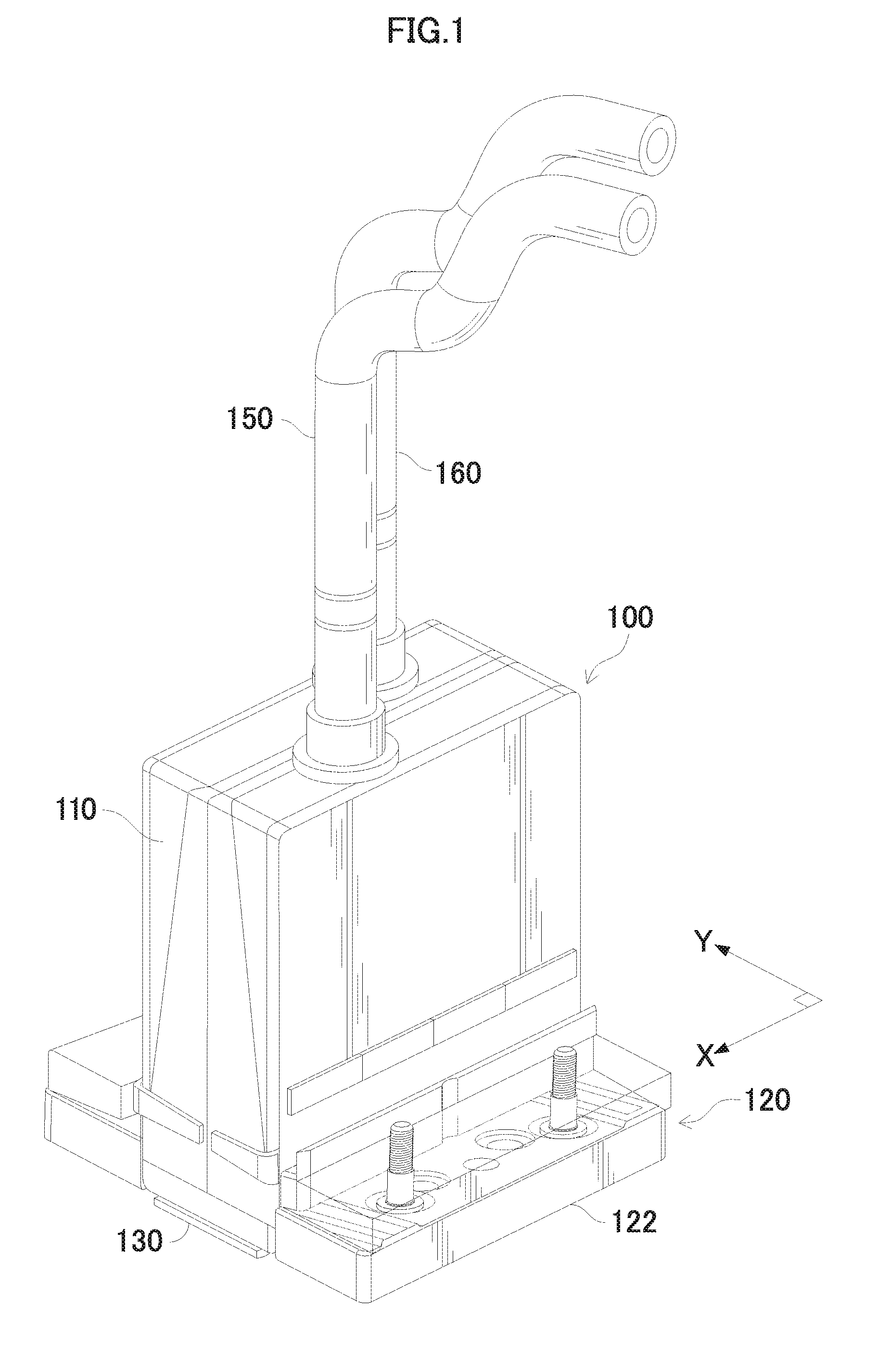
[0061]FIG. 1 is a perspective diagram of a droplet ejection head 100. The droplet ejection head 100 includes: a casing 110; a mounting assembly 120, which has a mounting component 122; and a substrate 130, which is attached to the bottom of the casing 110. The substrate 130 is made of silicon, such as single crystal silicon. Microfabricated fluid flow channels (see FIGS. 2 and 3) are formed in the substrate 130. A supply tube 150 and a return tube 160 are connected to a liquid tank 191 (not shown in FIG. 1, and shown in FIG. 8), and are connected to the droplet ejection head 100.

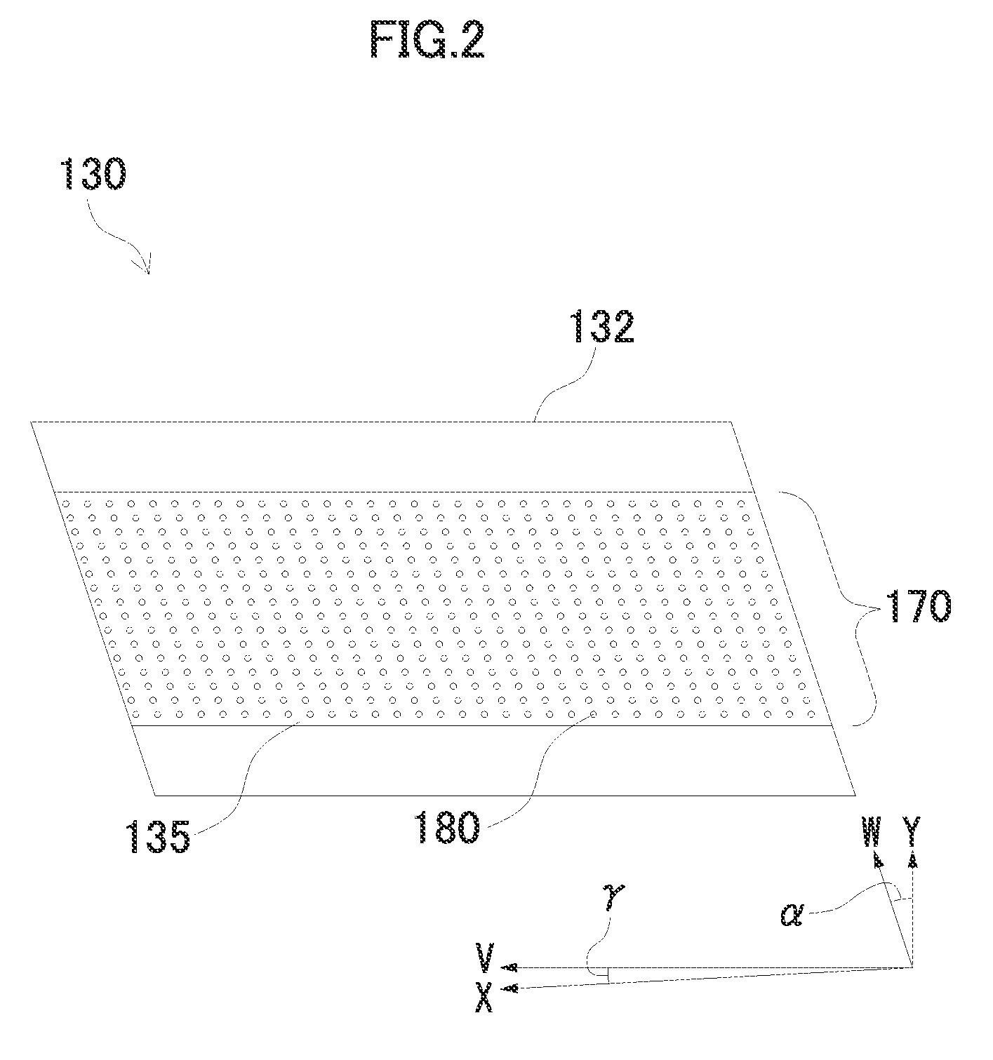
[0062]FIG. 2 shows the bottom surface of the substrate 130. The substrate 130 includes a nozzle layer 132, and the nozzle layer 132 has a nozzle face 135. The nozzle face 135 includes a plurality of columns 170 of nozzles 180. The nozzle face 135 has a quadrilateral shape, and has long edges in a V direction that is at an angle of γ relative to the X direction. The nozzle face 135 has short edges in a W dire...

second embodiment

[0082]FIG. 9A is a plan view perspective diagram of a substrate 330 of a droplet ejection head according to the second embodiment of the present invention, and FIG. 9B is a cross-sectional diagram along line 9B-9B in FIG. 9A. In FIGS. 9A and 9B, elements which are the same as or similar to those in the first embodiment are denoted with the same or similar reference numerals and description thereof is omitted here.

[0083]The droplet ejection head according to the second embodiment differs from the first embodiment in that a dummy pressure chamber 322, which has no nozzle as shown in FIG. 9B, is arranged on the side of the droplet ejection unit adjacent to the first main flow channel 211, in other words, the side adjacent to the bubble collection section 231.

[0084]According to the droplet ejection head of the second embodiment, it is possible to generate bubbles in the dummy pressure chamber, which does not contribute to image formation. By repeating pressurization and depressurization...

third embodiment

[0089]A droplet ejection head according to the third embodiment has a nozzle that is connected to the connection channel of the droplet ejection unit that does not contribute to image formation, in the droplet ejection head in the second embodiment. In other words, the structure of the droplet ejection unit is similar to the structure of the first embodiment and is therefore not shown in the drawings. The fact that the droplet ejection unit not contributing to image formation is used to introduce bubbles differs from the first embodiment.

[0090]According to the droplet ejection head in the third embodiment, since bubbles can be introduced through the ejection port that does not contribute to image formation, then it is possible to collect bubbles in the common return channel readily. As a method of introducing bubbles from the ejection port, it is possible to employ a similar method to that of the first embodiment. Moreover, in the third embodiment, in contrast to the first embodimen...


PUM


Abstract

The droplet ejection head includes: a plurality of droplet ejection units which include ejection ports through which droplets of liquid are ejected, pressure chambers which are connected to the ejection ports through connection channels, drive elements which apply pressure to the liquid in the pressure chambers, supply channels through which the liquid is supplied to the pressure chambers, and return channels through which the liquid is returned from the connection channels; a common supply channel through which the liquid is supplied to the supply channels; and a common return channel through which the liquid is returned from the return channels, the common return channel including a stagnant flow region having a bubble collection section where bubbles are collected, wherein pressure variation occurring in each pressure chamber when ejecting a droplet of the liquid propagates more readily in the common return channel than in the common supply channel.

Description

BACKGROUND OF THE INVENTION[0001]1. Field of the Invention[0002]The present invention relates to a droplet ejection head having a circulation flow channel, a droplet ejection apparatus including the droplet ejection head, and a method of collecting bubbles in the droplet ejection head.[0003]2. Description of the Related Art[0004]There are known inkjet type print heads (inkjet heads) in which ink is supplied to a plurality of pressure chambers from a common flow channel storing the ink, each pressure generating element is actuated to apply pressure to the ink inside a corresponding one of the pressure chambers, and the ink is ejected from a nozzle connected to the pressure chamber. In these print heads, a phenomenon known as fluid cross-talk is liable to occur whereby the pressure change affects the adjacent nozzles (and in particular, the meniscus therein) through the flow channels, and hence a structure which impedes the transmission of pressure to adjacent nozzles by arranging dam...

Claims


Application Information

Patent Timeline
IPC IPC(8): B41J2/19
CPCB41J2/04525B41J2/04581B41J2/04588B41J2/14233B41J2202/12B41J2/17596B41J2002/14459B41J2202/07B41J2/175
Inventor NISHIKAWA, BAKUSETO, SHINJIMORITA, NAOKI
Owner FUJIFILM CORP
Why Eureka
Try Eureka