LED lamp

a technology of led lamps and led lamps, applied in the field of led lamps, can solve the problems of improper illumination of the desired area of the lamp,

Inactive Publication Date: 2011-04-14
IRIS OHYAMA
View PDF0 Cites 38 Cited by
  • Summary
  • Abstract
  • Description
  • Claims
  • Application Information

AI Technical Summary

Benefits of technology

[0006]The present invention is proposed under the circumstances described above. It is therefore an object of the present invention to provide an LED lamp that can change the emission direction of light in the state attached to a general-use fluorescent lighting fixture.

Problems solved by technology

Therefore, depending on the orientation of the LED lamp X in the state attached to a fluorescent lighting fixture, a desired region may not be properly illuminated with light.

Method used


Image

  • LED lamp
  • LED lamp
  • LED lamp

Examples


first embodiment

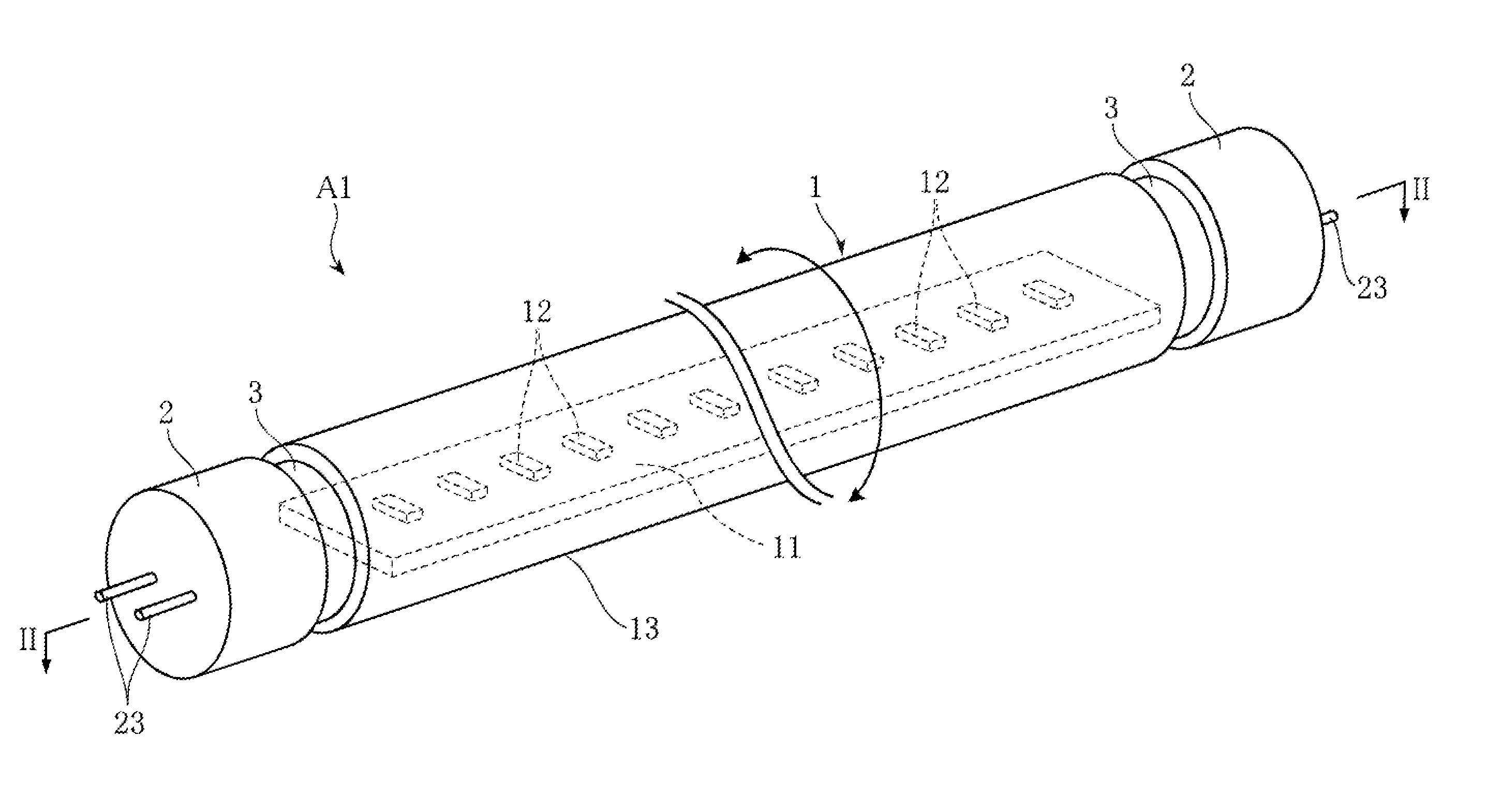
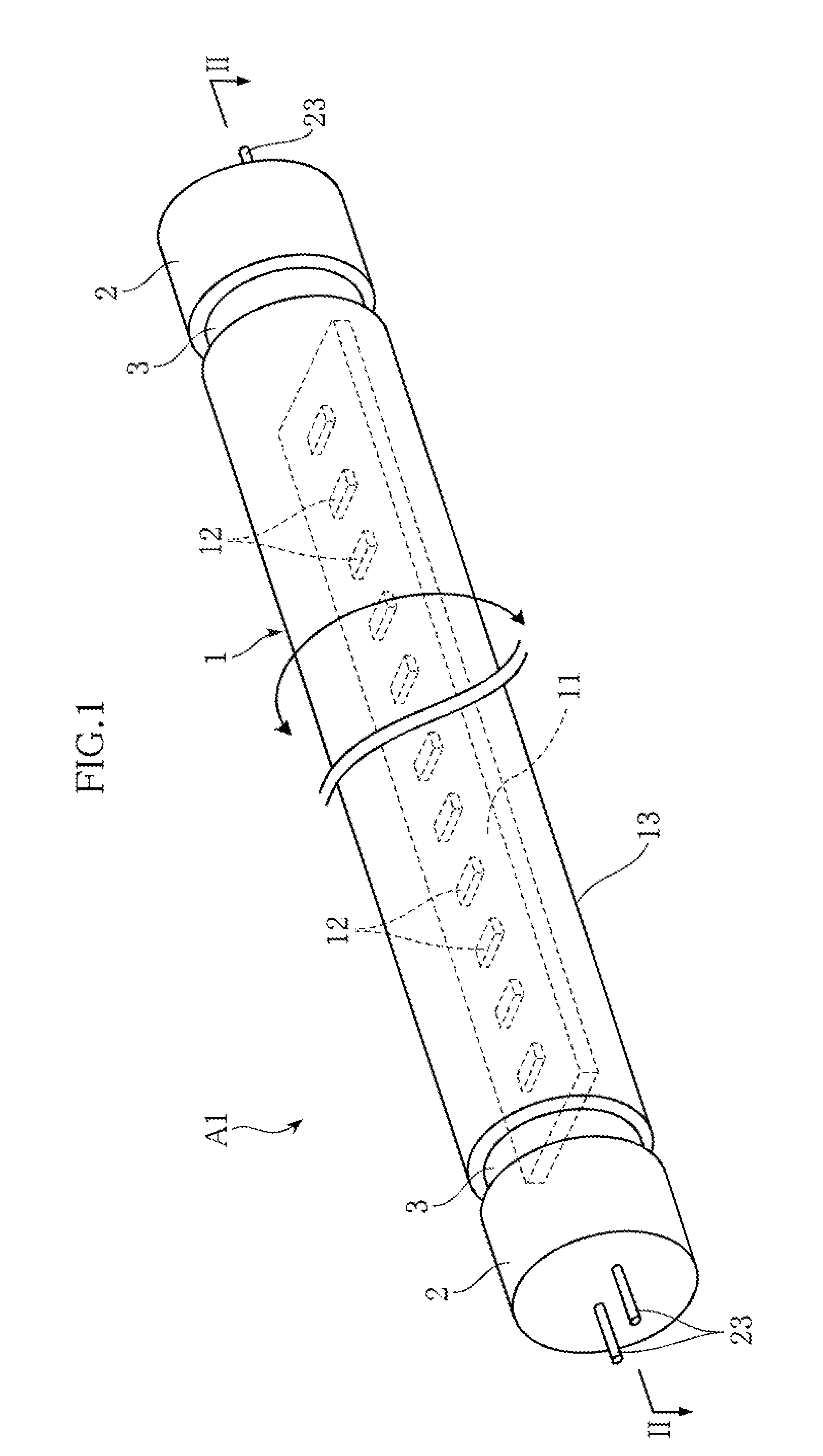
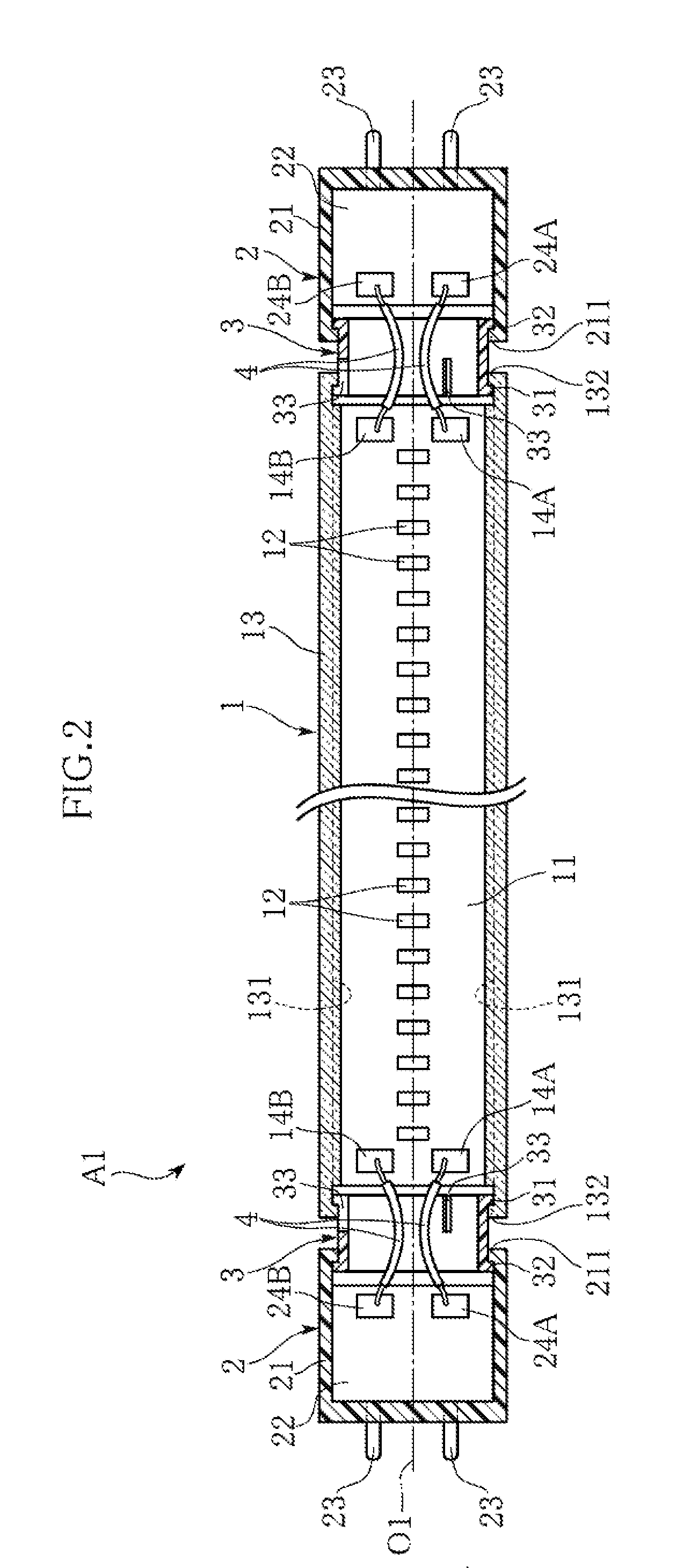
[0020]FIGS. 1 and 2 show an LED lamp according to the present invention. The LED lamp A1 of this embodiment includes an LED unit 1 in the shape of a straight tube, a pair of bases 2 and rotational shafts 3. For instance, the LED lamp is used as attached to a general-use fluorescent lighting fixture, as a substitute for a straight-tube fluorescent lamp.

[0021]The LED unit 1 includes a substrate 11 in the shape of an elongated rectangle, a plurality of LED modules 12 mounted on the substrate 11, and a cylindrical case 13 accommodating the substrate 11. The substrate 11 is fixed to the case 13 by e.g. fitting the longitudinally extending edges of the substrate into engagement grooves 131 formed at the inner circumference of the case 13. As the LED modules 12, e.g. a white, packaged LED is suitably used. The plurality of LED modules 12 are connected in series to each other by e.g. a wiring, not shown. A pair of terminals 14A and 14B, which are electrically connected to the wiring, are pr...

second embodiment

[0032]FIG. 3 shows an LED lamp according to the present invention. The LED lamp A2 of this embodiment is different from the LED lamp A1 of the foregoing embodiment in connecting structure of the LED unit 1 and the bases 2. Specifically, an additional substrate 15 is provided at each end of the substrate 11 of the LED unit 1 in the longitudinal direction. The substrate 15 is disposed in such a manner that its in-plane direction is perpendicular to the axis O1. The circuit board 22 of the base 2 is disposed to face the substrate 15.

[0033]A cylindrical shaft 16 and an elastic conductive member 17 are provided on the substrate 15 at the surface 15a that faces the circuit board 22. The center axis of the cylindrical shaft 16 corresponds to the axis O1. The cylindrical shaft 16 is provided with a terminal 18A, which comprises e.g. a metal film, on the inner surface. The terminal 18A is electrically connected to the terminal 14A of the substrate 11 via a wire 41 and so on. The elastic cond...

third embodiment

[0036]FIG. 4 shows an LED lamp according to the present invention. The LED lamp A3 of this embodiment is different from the LED lamp A2 of the foregoing embodiment in electrical connection structure of the substrate 15 of the LED unit 1 and the circuit board 22 of the base 2. Specifically, an outer cylindrical shaft 16′ and a pin 19 are provided on the surface 15a of the substrate 15. The outer cylindrical shaft 16′ has a cylindrical shape having a center axis corresponding to the axis O1, and is provided with a terminal 18A on the inner surface. The pin 19 has a center axis corresponding to the axis O1, and is provided with a terminal 18B on the outer surface. A rotational shaft 3″ is provided on the surface 22a of the circuit board 22. The rotational shaft 3″ has a cylindrical shape having a center axis corresponding to the axis O1, and is provided with a terminal 24A on the outer surface and a terminal 24B on the inner surface.

[0037]The outer cylindrical shaft 16′, the pin 19 and...


PUM


Abstract

An LED lamp A1 includes an LED unit 1 in the shape of a straight tube with a plurality of LED modules 12 fixed therein, and also includes a pair of bases 2 that receive electric power from outside and are attached to the ends of the LED unit 1 spaced in the longitudinal direction of the LED unit. The LED unit 1 and the bases 2 are rotatable relative to each other about an axis extending in the longitudinal direction. With this arrangement, the direction of light emission can be changed, with the LED lamp attached to a general-use fluorescent lighting fixture.

Description

TECHNICAL FIELD[0001]The present invention relates to an LED lamp that uses an LED as the light source and that is suitable for use as a substitute for a fluorescent lamp.BACKGROUND ART[0002]FIG. 5 shows a conventional LED lamp in a sectional view (see Patent Document 1 for example). The LED lamp X illustrated in the figure includes a substrate 91 in the shape of an elongated rectangle, a plurality of LEDs 92 mounted on the substrate 91, a tube 93 accommodating the substrate 91, terminals 94, and a circuit 95 for lighting the LEDs 92. The substrate 91 is formed with a wiring (not shown) that electrically connects the LEDs 92 and the terminals 94 to each other. When the terminals 94 are fitted into insertion ports of sockets of a general-use fluorescent lighting fixture, the LEDs 92 can be turned on. Since LEDs 92 have lower power consumption and a longer life, the use of LED lamp X as a substitute for a fluorescent lamp is expected to provide advantages in terms of the cost and envi...

Claims


Application Information

Patent Timeline
Patent Type & Authority Applications(United States)
IPC IPC(8): F21S4/00
CPCF21K9/58F21V14/02F21V19/02F21V23/002F21Y2103/003F21K9/175F21Y2101/02F21K9/272F21K9/275F21K9/65F21Y2103/10F21Y2115/10
Inventor OSAWA, HIDEHARU
Owner IRIS OHYAMA
Why Eureka
Try Eureka