
Image forming apparatus, image forming method, and computer program product

a technology of image forming and image forming, applied in the field of image forming apparatus, image forming method, and computer program product, can solve problems such as difficulty in improving position accuracy for alignmen

Inactive Publication Date: 2011-04-14
RICOH KK
View PDF8 Cites 44 Cited by
  • Summary
  • Abstract
  • Description
  • Claims
  • Application Information

AI Technical Summary

Benefits of technology

[0008]It is an object of the present invention to at lea...

Problems solved by technology

Therefore, there is a problem in that it is difficult to improve position accuracy for alignment at the time of performing full-color printing by using both the direct transfer system and the indirect transfer system.

Method used


Image

  • Image forming apparatus, image forming method, and computer program product
  • Image forming apparatus, image forming method, and computer program product
  • Image forming apparatus, image forming method, and computer program product

Examples


Embodiment Construction

[0027]Exemplary embodiments of the present invention will be explained in detail below with reference to the accompanying drawings.

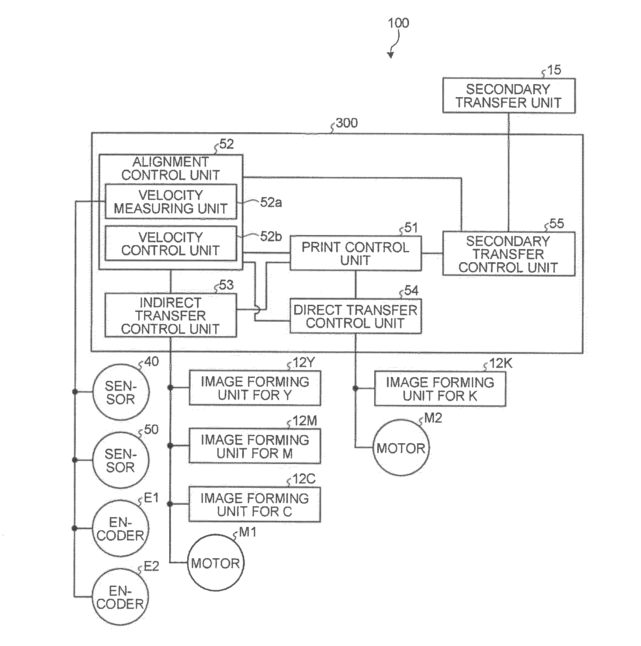
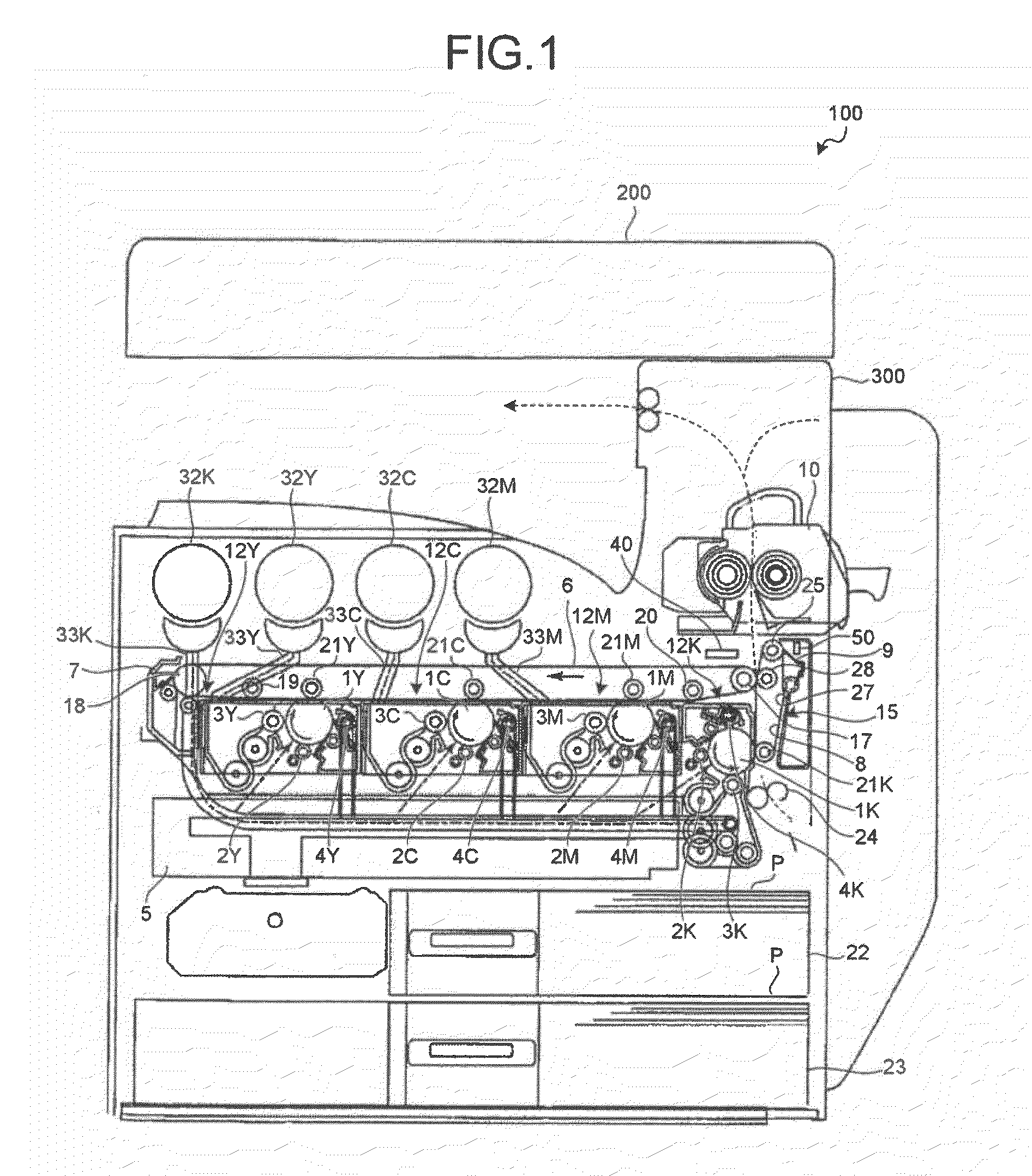
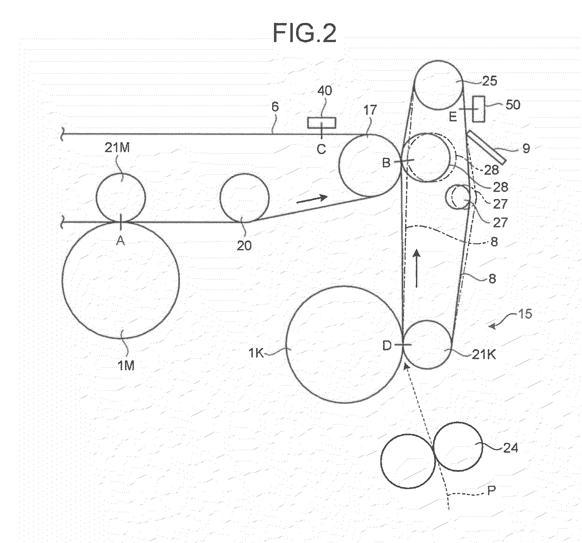
[0028]An embodiment of the present invention is explained below with reference to FIGS. 1 to 14. The embodiment is an example in which an image forming apparatus is embodied in what is called a color digital multifunction peripheral (hereinafter, simply referred to as an MFP), which has, in combination, a copy function, a facsimile (FAX) function, a print function, a scanner function, a function of distributing an input image (an image of an original read by using the scanner function or an image input by using the FAX function), and the like.

[0029]FIG. 1 is a schematic configuration diagram of an MFP 100 according to the embodiment of the present invention. As illustrated in FIG. 1, the MFP 100 is made up of a scanner unit 200 that is an image reading device and a printer unit 300 that is an image printing device. The scanner unit 200 and the printer un...


PUM


Abstract

An image forming apparatus includes: a transfer-sheet conveying member that rotates to convey a transfer sheet; a first image forming unit that directly transfers a color image onto the transfer sheet; an intermediate transfer member that rotates while an image is transferred thereon; a second image forming unit that transfers images onto the intermediate transfer member; a secondary transfer unit that transfers the images on the intermediate transfer member onto the transfer sheet; a measuring unit that measures a surface velocity of the transfer-sheet conveying member and the intermediate transfer member; and a control unit that performs phase matching control by accelerating or decelerating the transfer-sheet conveying member or the intermediate transfer member so as to match a phase of fluctuation of the measured surface velocity of the transfer-sheet conveying member and a phase of fluctuation of the measured surface velocity of the intermediate transfer member.

Description

CROSS-REFERENCE TO RELATED APPLICATIONS[0001]The present application claims priority to and incorporates by reference the entire contents of Japanese Patent Application No. 2009-237099 filed in Japan on Oct. 14, 2009.BACKGROUND OF THE INVENTION[0002]1. Field of the Invention[0003]The present invention relates to an image forming apparatus, an image forming method, and a computer program product.[0004]2. Description of the Related Art[0005]In recent years, in the field of an electrophotographic color image forming apparatus, there has been proposed an image forming apparatus that uses both a direct transfer method for directly transferring an image formed on a photosensitive element onto a sheet and an indirect transfer method for temporarily transferring images formed on a plurality of photosensitive elements for each color onto an intermediate transfer member so as to superimpose the images one on top of the other and then transfer the superimposed images onto a sheet (see, for exa...

Claims


Application Information

Patent Timeline
IPC IPC(8): G03G15/01
CPCG03G2215/00156G03G15/0194G03G15/6567G03G2215/1623
Inventor KOSAKO, JUNISHII, SHIGEYUKIENAMI, TAKASHIKOBAYASHI, NOBUYUKIKAWASE, NATSUKOKAMEKURA, TAKAHIROMIYAKAWA, TAKAHIROTANIGUCHI, MIYO
Owner RICOH KK
Learn More