
Fixing device and image forming apparatus

Inactive Publication Date: 2011-04-14
KONICA MINOLTA BUSINESS TECH INC
View PDF8 Cites 4 Cited by
  • Summary
  • Abstract
  • Description
  • Claims
  • Application Information

AI Technical Summary

Benefits of technology

[0009]The present invention was achieved in view of the aforesaid problems, and the object of the present invention is to prevent image failures from occurring in the nip section so as to improve fixing accuracy.

Problems solved by technology

Since the abovementioned fixing device of the belt-nip system has a configuration to press the fixing belt to the heating roller by the pressing member, the longer nip width results in more uneveness of sheet conveying speed in the nip section.
Thus, there has been a problem that a sheet behavior becomes unstable so that the potentials of image misalignment and / or sheet wrinkles are increased.

Method used


Image

  • Fixing device and image forming apparatus
  • Fixing device and image forming apparatus
  • Fixing device and image forming apparatus

Examples


examples

[0061]Hereinafter, the fixing device according to the embodiment will be described in detail by citing examples. The embodiment of the present invention is not limited to these examples.

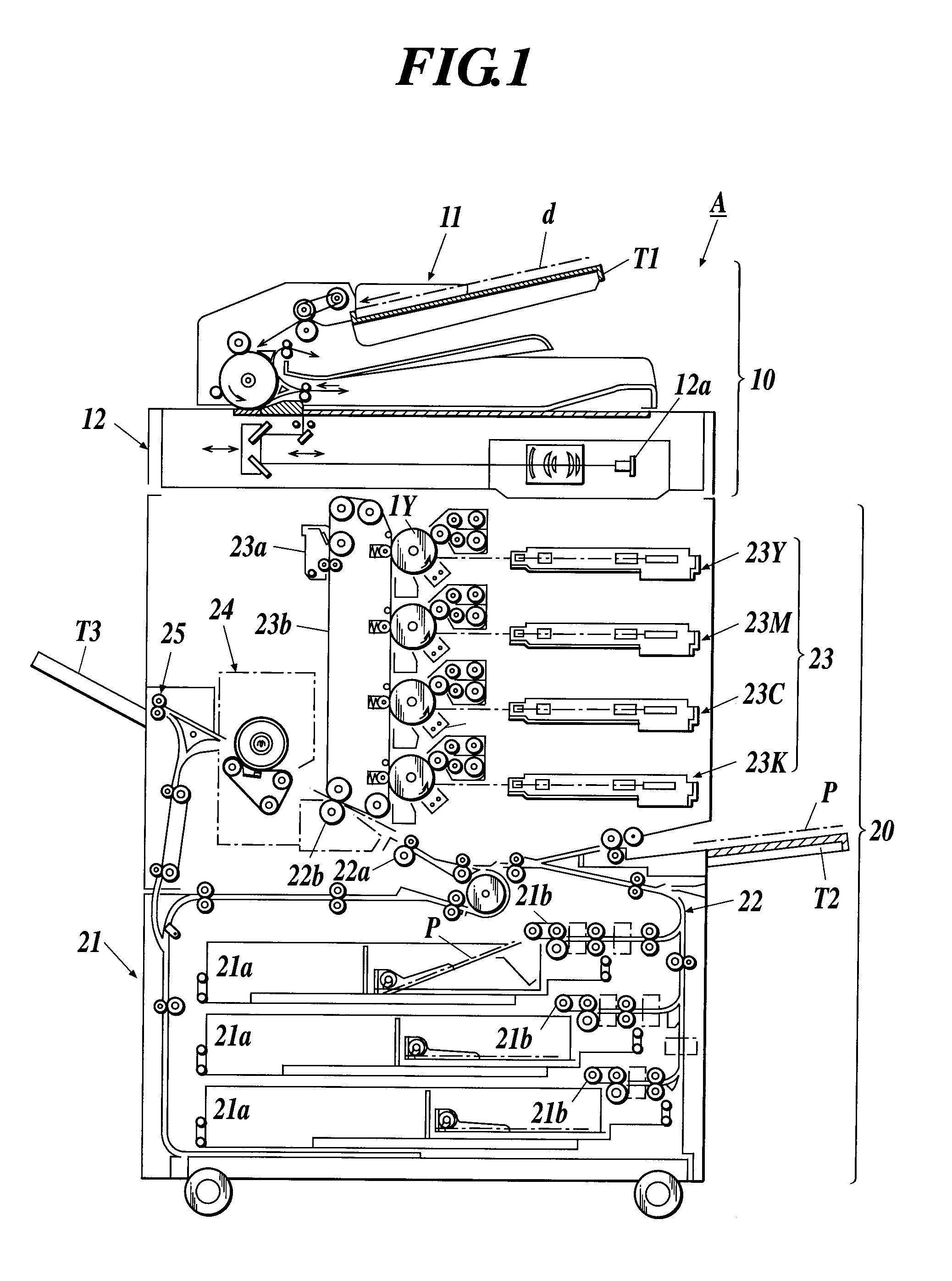
[0062]In this example, in the image forming apparatus shown in FIG. 1, by using a plurality of fixing devices whose configurations of the first, second, and third pads are different from one another, pressure distributions in the respective nip sections were performed, and the images after fixing process were observed to evaluate image qualities.

[0063]FIGS. 3A-3F show the schematic configuration diagrams of the pressurizing sections in which the first, second, and third pads have different configurations from one another, and FIG. 4 shows pressure distributions in the nip sections of the fixing devices respectively equipped with the pressurizing sections shown in FIGS. 3A-3F. The length of the upstream portion of the nip section in the sheet conveying direction was 15% (5 [mm] in this example) of the...


PUM


Abstract

Disclosed is a fixing device including: a heating section; a pressure contact section to form a nip section with the heating device and to pressure a sheet so that the sheet contacts with the heating section; and a pressurizing section to add a pressurizing force to the sheet through the pressure contact section and to make the nip section be formed between the heating section and the pressure contact section; wherein the pressurizing section adds the higher pressurizing force to an upstream portion and a downstream portion of the nip section than the pressurizing force added to a central portion of the nip section in a sheet conveying direction, and adds the higher pressurizing force to the downstream portion than the pressurizing force added to the upstream portion.

Description

BACKGROUND[0001]1. Field of the Invention[0002]The present invention relates to a fixing device and an image forming apparatus.[0003]2. Description of Related Art[0004]Generally, in an electrophotographic image forming apparatus, a surface of an image carrier such as a photoconductive drum is charged to a predetermined potential, and image exposure is performed thereon to form an electrostatic latent image. Then, the latent image on the surface of the photoconductive drum is developed with developer (toner) by a developing member to be visualized as a toner image. The obtained toner image is transferred onto a sheet which has been conveyed to the photoconductive drum, the sheet which supports the toner image thereon is conveyed to a fixing device, and an unfixed toner image on the sheet is fixed by the fixing device so that a print image is obtained on the sheet.[0005]The fixing device of the image forming apparatus is equipped with a heating section (heating roller) and a pressure ...

Claims


Application Information

Patent Timeline
IPC IPC(8): G03G15/20
CPCG03G15/206G03G2215/2009
Inventor MATSUMOTO, HIROSHI
Owner KONICA MINOLTA BUSINESS TECH INC
Features
  • Generate Ideas
  • Intellectual Property
  • Life Sciences
  • Materials
  • Tech Scout
  • Unparalleled Data Quality
  • Higher Quality Content
  • 60% Fewer Hallucinations
Learn More