

Dynamic table look-up based voltage regulator control
a voltage regulator and dynamic table technology, applied in the field of dynamic voltage control of computing systems, can solve the problems of affecting the latency of the microprocessor, time-consuming and labor-intensive to communicate a target voltage level for one or more power planes over serial interfaces
- Summary
- Abstract
- Description
- Claims
- Application Information
AI Technical Summary
Benefits of technology
Problems solved by technology
Method used
Image

Examples
Embodiment Construction
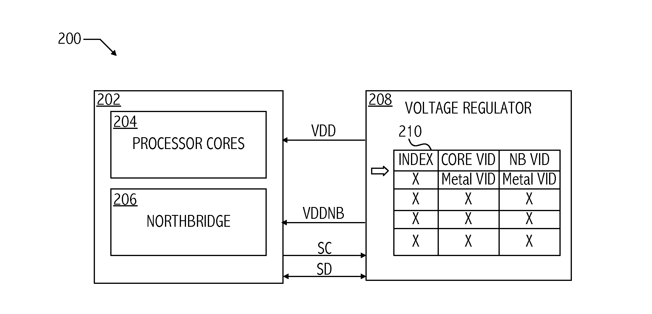
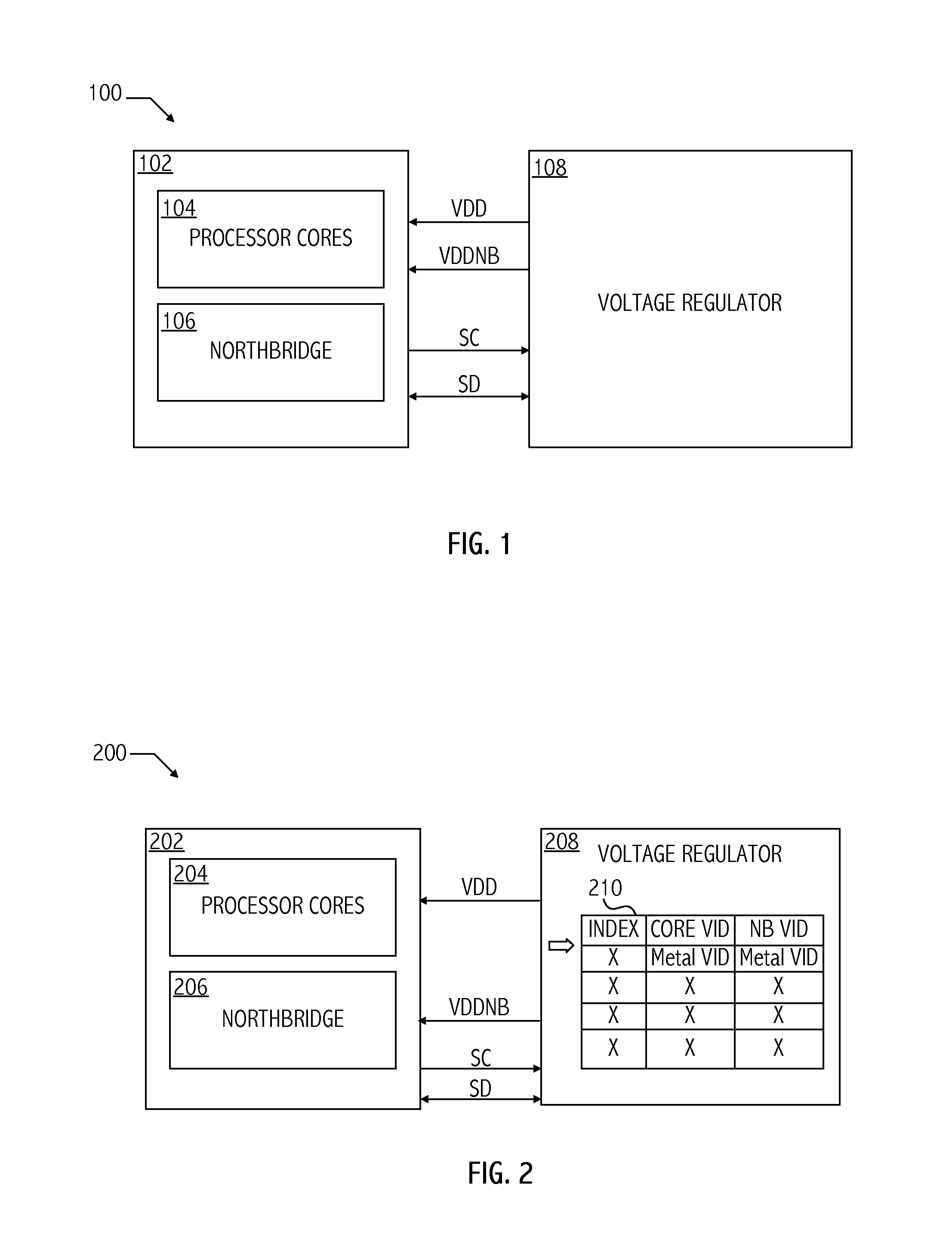
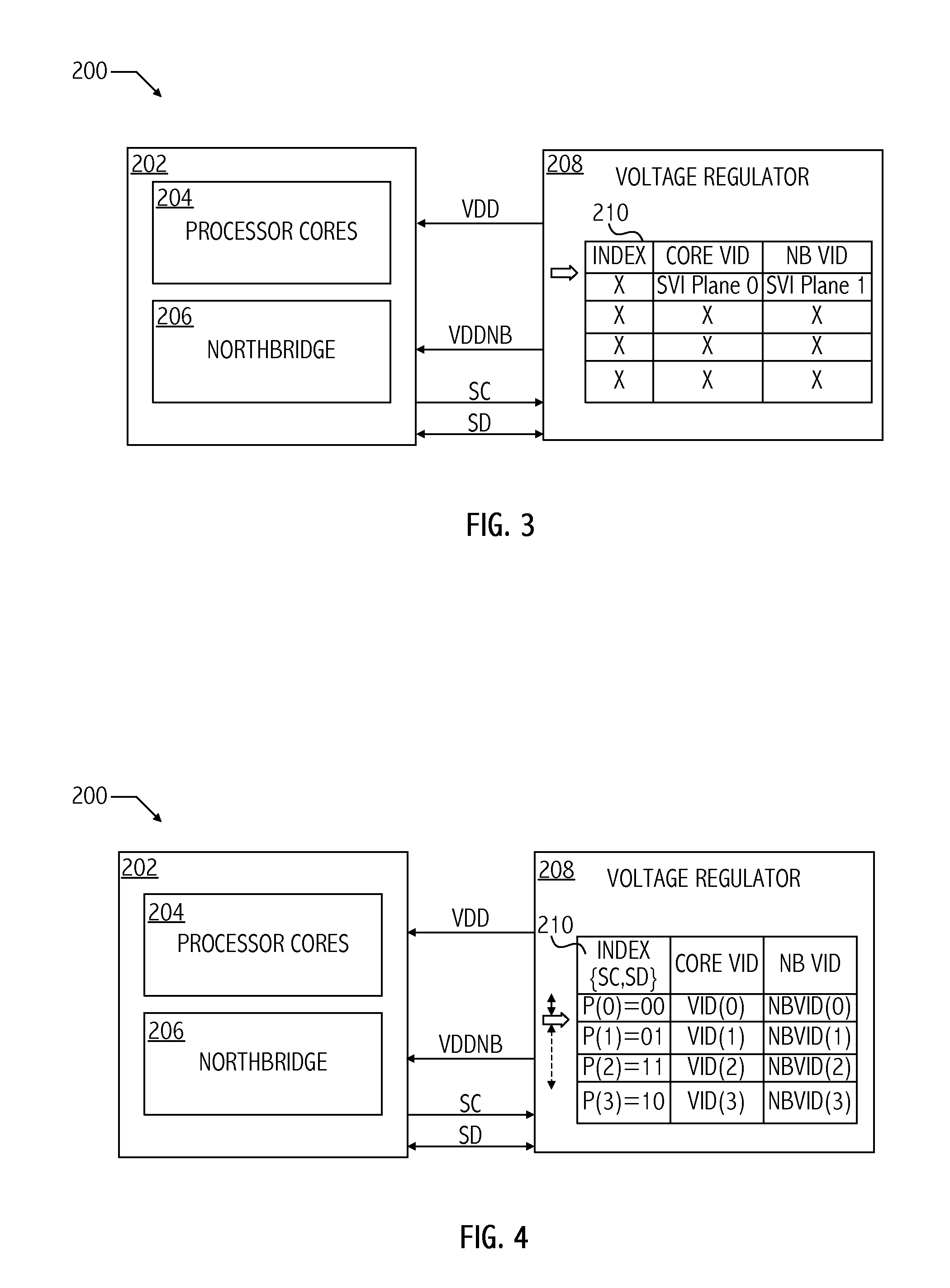
[0006]A technique for dynamically controlling microprocessor power plane voltage levels includes storing, in a memory on a voltage regulator, voltage control identifiers in a table accessible according to performance state. In at least one embodiment of the invention, a method includes transitioning a voltage output of a voltage regulator to a next voltage level associated with a next performance state of a processor adapted to be coupled to the voltage regulator based on a performance state indicator received by the voltage regulator and a corresponding entry of a performance state table. In at least one embodiment, the method includes loading performance state table entries into a storage device on the voltage regulator circuit.
[0007]In at least one embodiment of the invention, an apparatus includes a voltage regulator configured to receive an indicator of a next performance state of a processor. The voltage regulator includes an interface circuit configured to receive the indicat...
PUM
 Abstract
Description
Claims
Application Information