High input voltage, high efficiency, fast transient voltage regulator module (VRM)

a voltage regulator module, high efficiency technology, applied in the direction of dc-dc conversion, power conversion systems, climate sustainability, etc., can solve the problems of high input vrm topologies, low efficiency or slow transient response, and low efficiency

Inactive Publication Date: 2003-07-08
VIRGINIA TECH INTPROP INC
View PDF1 Cites 29 Cited by
  • Summary
  • Abstract
  • Description
  • Claims
  • Application Information

AI Technical Summary

Problems solved by technology

Today's high input VRM topologies, with or without isolation, have low efficiency or slow transient response.
If the high input-voltage VRMs don't have an isolation transformer to adjust their duty cycle their efficiency is very low, like the synchronous rectifier buck converter.
Although some high input-voltage VRMs have isolation transformers to adjust duty cycle, like forward and flyback VRMs, their efficiency is lower than that of the proposed topology.
Other high input-voltage isolated VRM topologies, like flyback forward and asymmetrical half bridge VRMs, have suitable effic

Method used


Image

  • High input voltage, high efficiency, fast transient voltage regulator module (VRM)
  • High input voltage, high efficiency, fast transient voltage regulator module (VRM)
  • High input voltage, high efficiency, fast transient voltage regulator module (VRM)

Examples


Embodiment Construction

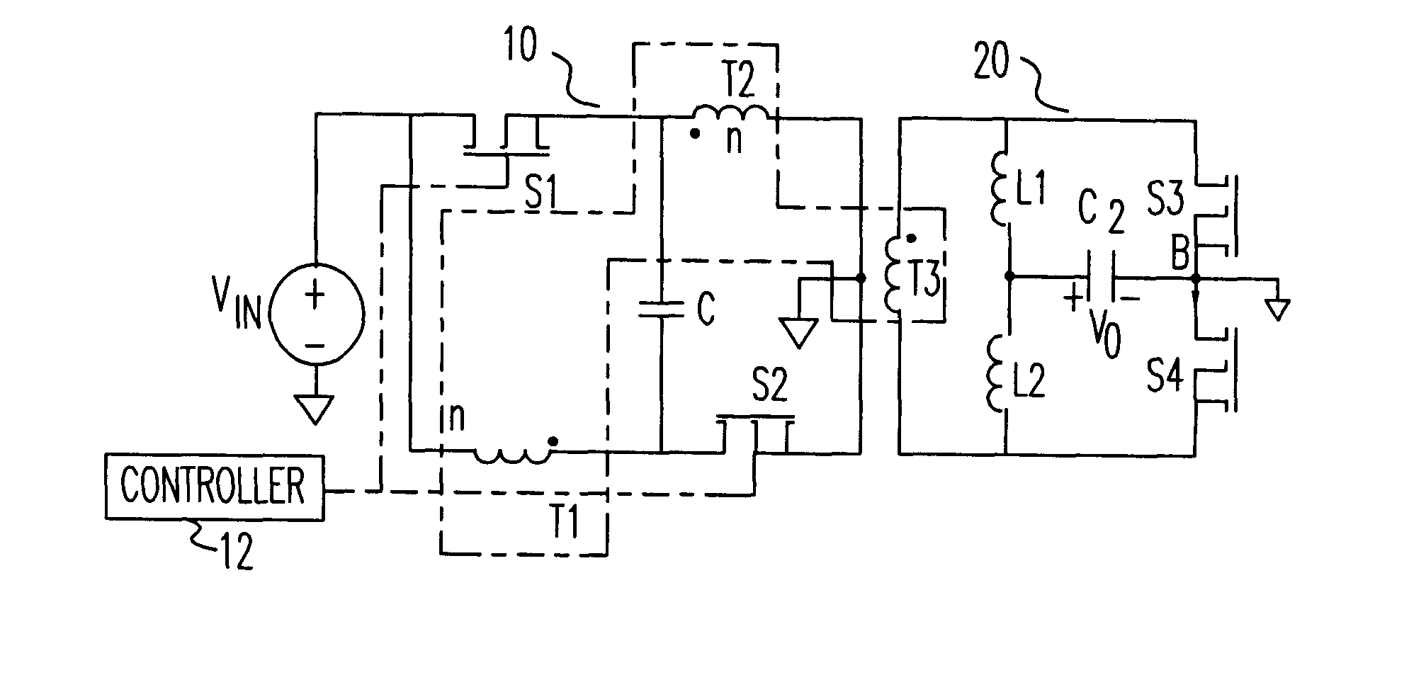
Referring now to the drawings, and more particularly to FIG. 7 there is shown the novel high input-voltage VRM topology--push pull forward converter according to the present invention. According to the invention, the primary side 10 comprises dual switches, S1 and S2, and transformer windings, T1 and T2, alternately connected in a loop with a capacitor C connected between any of two interleaved terminations. A voltage source Vin is connected between the switch S1 and the transformer T1. Similarly, a node between switch S2 and transformer T2 is connected to ground. The two primary windings, T1 and T2, have the same number of turns. The secondary side 20 comprises a current doubler structure. The secondary winding T3 connects to the terminations of two inductors, L1 and L2, and two synchronous switches, S3 and S4. The two inductors, L1 and L2, are connected together (point A). And the two switches are connected together (point B). The output is taken between points A and B.

FIG. 8 show...


PUM


Abstract

A high input-voltage push-pull forward voltage regulator module (VRM) has high efficiency and fast transient response. The VRM has a primary side wherein two switches and two primary transformer windings are alternately connected in a loop. A capacitor is connected between any of two interleaved terminations. The remaining two terminations are connected to input and ground respectively. The two primary transformer windings have the same number of turns. A number of secondary sides may be used such as, for example, a half wave rectifier or a center tapped secondary. The high input-voltage push-pull forward VRM has high efficiency and fast transient-response with reduced filter capacitance and inductance. Its magnetic components can be easily integrated. As a result, very high power density can be achieved. The device die size needed to achieve the required efficiency is reduced. And control is simple. Therefore, this topology is very cost effective.

Description

1. Field of the InventionThe present invention generally relates to a high input voltage, high efficiency, fast transient voltage regulator module and, more particularly, to a push-pull forward converter for driving low voltage, high current loads such as computer microprocessors.2. Description of the Prior ArtVoltage regulator modules (VRMs) are used for a variety of purposes, such as, for example, to provide power to microcomputer processors or other low voltage, high current loads. Today's high input VRM topologies, with or without isolation, have low efficiency or slow transient response. If the high input-voltage VRMs don't have an isolation transformer to adjust their duty cycle their efficiency is very low, like the synchronous rectifier buck converter. Although some high input-voltage VRMs have isolation transformers to adjust duty cycle, like forward and flyback VRMs, their efficiency is lower than that of the proposed topology. Other high input-voltage isolated VRM topolog...

Claims


Application Information

Patent Timeline
IPC IPC(8): H02M3/24H02M3/335
CPCH02M3/33569H02M3/33576H02M3/33592Y02B70/1475Y02B70/10
Inventor ZHOU, XUNWEILEE, FRED C.
Owner VIRGINIA TECH INTPROP INC
Why Eureka
Try Eureka