Apparatus and method for controlling voltage regulator and power supply apparatus

a voltage regulator and power supply technology, applied in the direction of electric variable regulation, process and machine control, instruments, etc., can solve the problems of large and expensive components generally not suitable for miniaturization, etc., and achieve the effect of improving the efficiency of the input voltage regulator

Inactive Publication Date: 2005-02-15
LENOVO INNOVATIONS LTD HONG KONG
View PDF2 Cites 30 Cited by
  • Summary
  • Abstract
  • Description
  • Claims
  • Application Information

AI Technical Summary

Benefits of technology

Therefore, an object of the present invention is to provide a method and circuitry ...

Problems solved by technology

However, the inductor tends to be a large and expensive...

Method used


Image

  • Apparatus and method for controlling voltage regulator and power supply apparatus
  • Apparatus and method for controlling voltage regulator and power supply apparatus
  • Apparatus and method for controlling voltage regulator and power supply apparatus

Examples


first embodiment

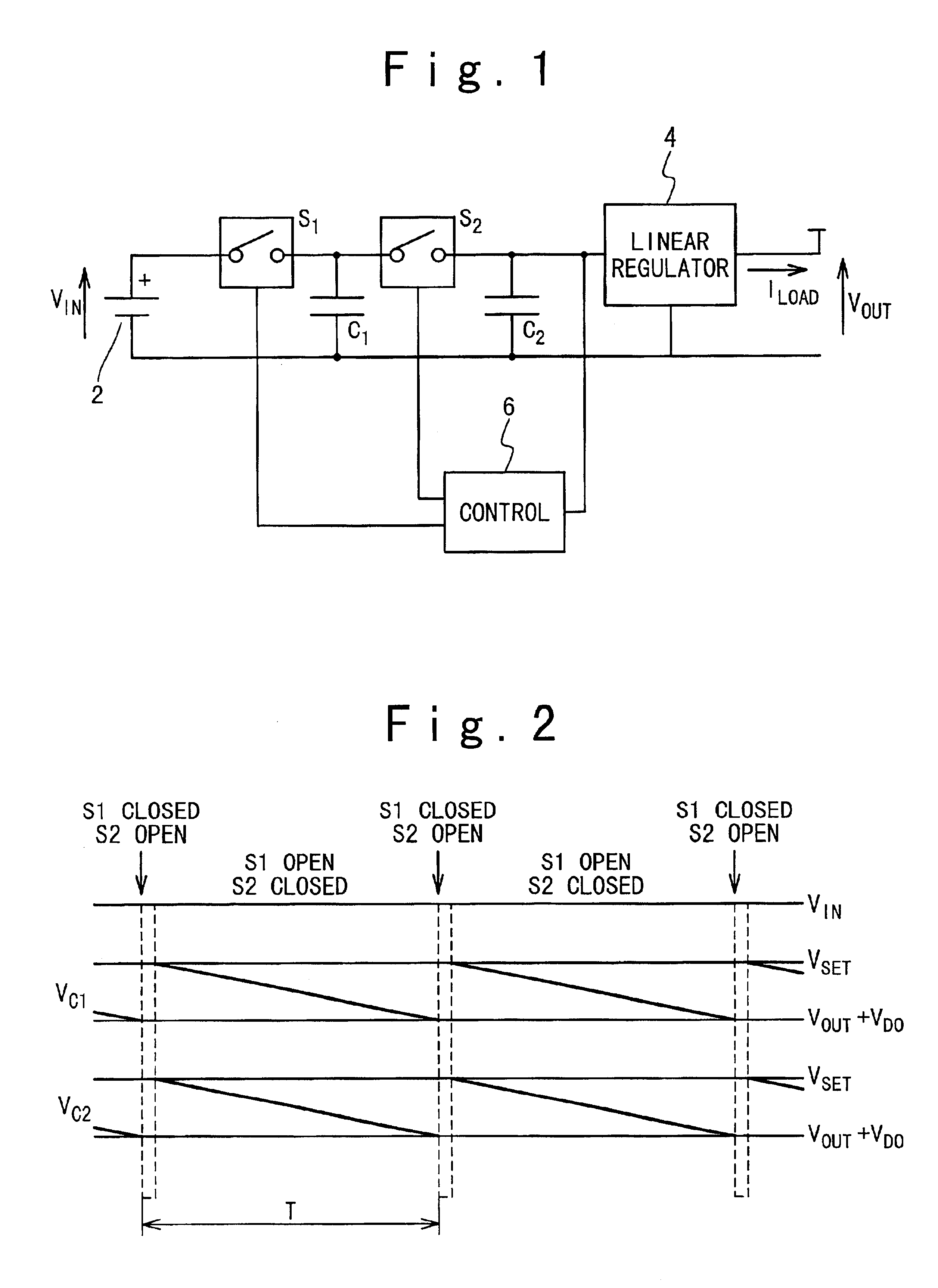
A control apparatus of a linear regulator according to the present invention is shown in FIG. 1. The control apparatus is comprised of a DC power supply or battery 2 which supplies an input voltage Vin. The power supply is connected in parallel with two capacitors C1 and C2. The capacitor C1 is separated from the voltage Vin by a switch S1. A further switch S2 separates the capacitors C1 and C2. A linear regulator 4 is connected across the circuit downstream of the capacitor C2 and has an output which produces a voltage Vout and a current Iload.

A control circuit 6 monitors the input voltage Vin to the linear regulator 4 and in response to the monitoring result, supplies control signals to the switches S1 and S2 which can be closed. The switch S1 when closed will enable the capacitor C1 to charge. The switch S2 when closed will allow the capacitor C2 to charge from the capacitor C1 at the same time as providing input charge to the linear regulator 4.

The control circuit 6 is responsiv...

second embodiment

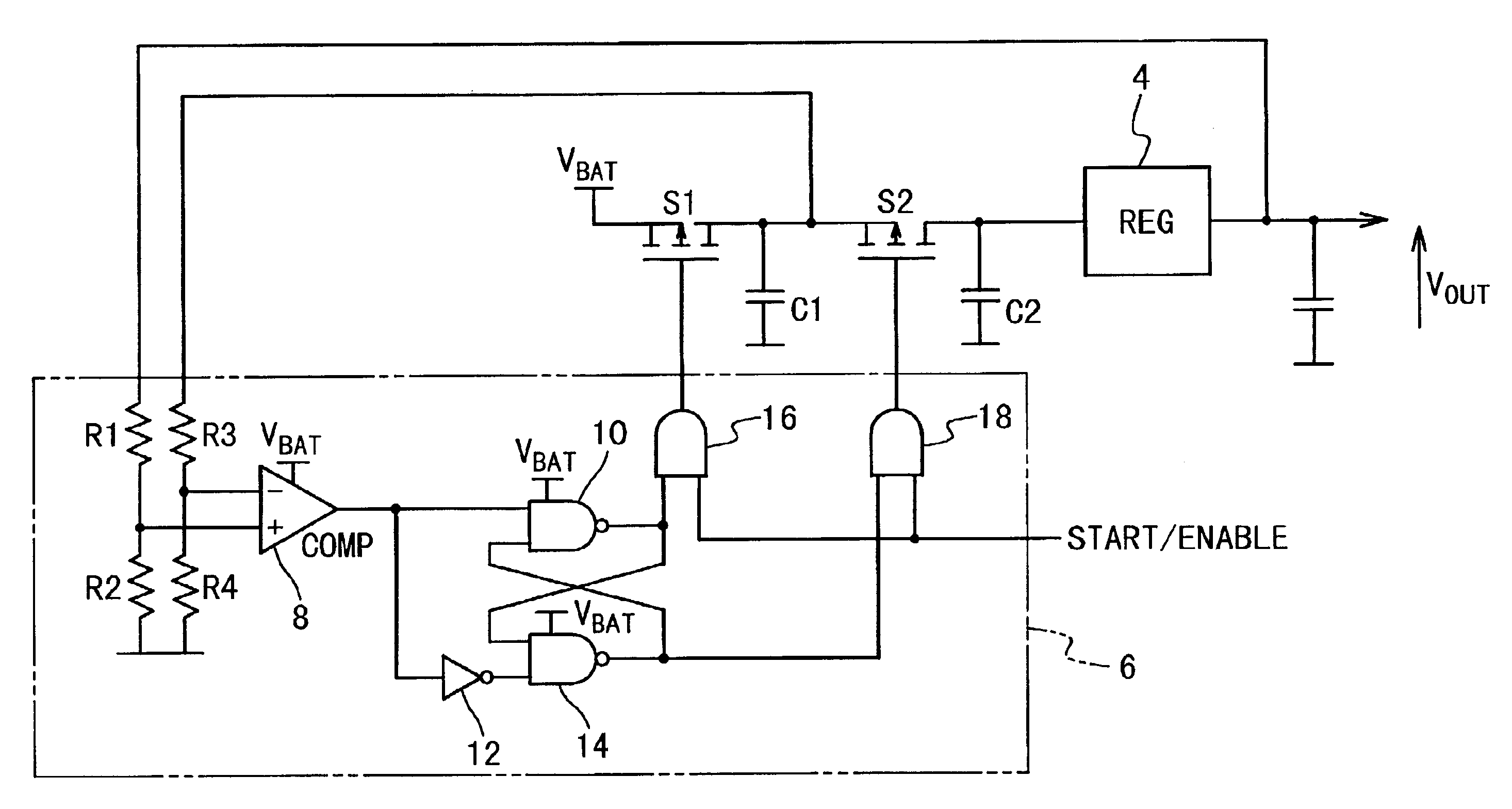
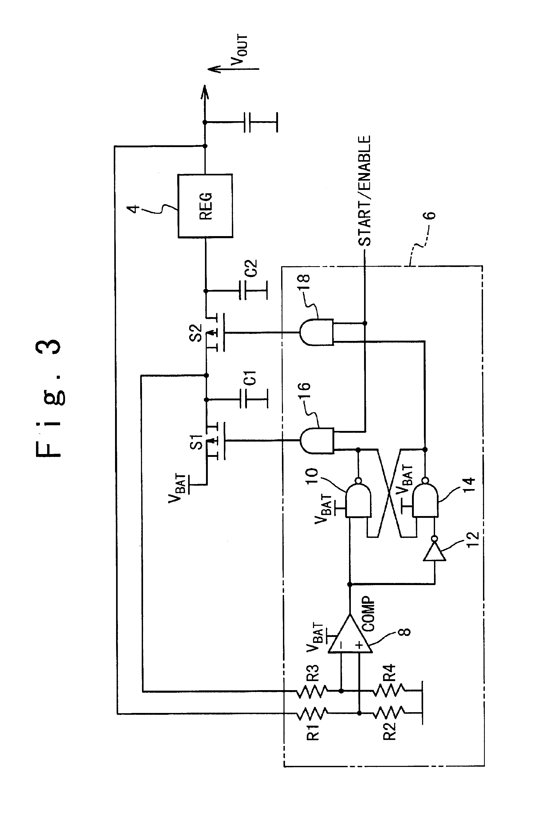
FIG. 3 shows the control apparatus of the regulator according to the present invention. The portion of the circuit corresponding to the control circuit 6 of FIG. 1 is shown in dotted outline. The switches S1 and S2 are P-channel FET devices. The feedback arrangement of the voltage which in FIG. 1 is from the input voltage to the linear regulator (given by the voltage on the capacitor C2) is in the embodiment replaced by feedback from the voltage on the capacitor C1 and from the voltage output of the regulator 4 for Vout. The output voltage Vout is the voltage input to a voltage divider R1 and R2 and the output of this divider is provided to one input of a comparator 8. The voltage on the capacitor C1 is fed by a further voltage divider R3 and R4 to the other inverted input of a comparator 8. The comparator has a hysteresis characteristic and outputs a pulse with a predetermined duration time when the output of the voltage divider R3 and R4 is lower than that of the voltage divider R...


PUM


Abstract

In a method for controlling a voltage regulator, first and second charge storage devices are switchably connected between a voltage source and the voltage regulator. The first storage device is switched into connection with the voltage source until the voltage on it reaches a predetermined level. The first storage device is disconnected from the voltage source and switched into connection with the second storage device and the voltage regulator until the voltage input to the voltage regulator falls below a predetermined level. The above operations are repeated.

Description

BACKGROUND OF THE INVENTION1. Field of the InventionThe present invention relates to an apparatus and method for controlling a linear voltage regulator.2. Description of the Related ArtLinear voltage regulators are well known electronic devices. They are used to produce a steady output voltage at a predetermined level from an input voltage which may vary. The input voltage is higher than the output voltage and heat is dissipated in the regulator. The power dissipated given a constant load current is proportional to the voltage drop between the input and the output. For example, in a battery operated system where the operating voltage of the circuitry is significantly lower than the battery voltage, reducing the power dissipation in the regulator will lead to improved battery life. It will also reduce the thermal efficiency requirements of the regulator thereby allowing a small and cheaper package and pass transistor to be used. Conventionally, power supply efficiency has been improv...

Claims


Application Information

Patent Timeline
IPC IPC(8): G05F1/10G05F1/607H02M3/04H02M3/07H02J1/00G05F1/563
CPCG05F1/607H02M3/07H02M2001/0045H02M1/0045
Inventor WALLIS, MARK
Owner LENOVO INNOVATIONS LTD HONG KONG
Why Eureka
Try Eureka