Fault tolerant voltage regulator module circuit for supplying core voltage and cache voltage to a processor

a voltage regulator and module circuit technology, applied in the field of fault tolerance voltage regulator module circuit for supplying core voltage and cache voltage to a processor, can solve the problems of processor failure or inoperativeness

Inactive Publication Date: 2001-02-13
HANGER SOLUTIONS LLC
View PDF14 Cites 30 Cited by
  • Summary
  • Abstract
  • Description
  • Claims
  • Application Information

AI Technical Summary

Problems solved by technology

When the voltage regulator modules supplying voltages supply a low voltage or become inoperative becaus

Method used


Image

  • Fault tolerant voltage regulator module circuit for supplying core voltage and cache voltage to a processor
  • Fault tolerant voltage regulator module circuit for supplying core voltage and cache voltage to a processor
  • Fault tolerant voltage regulator module circuit for supplying core voltage and cache voltage to a processor

Examples


Embodiment Construction

One preferred embodiment will be explained in detail referring to FIGS. 1 and 2.

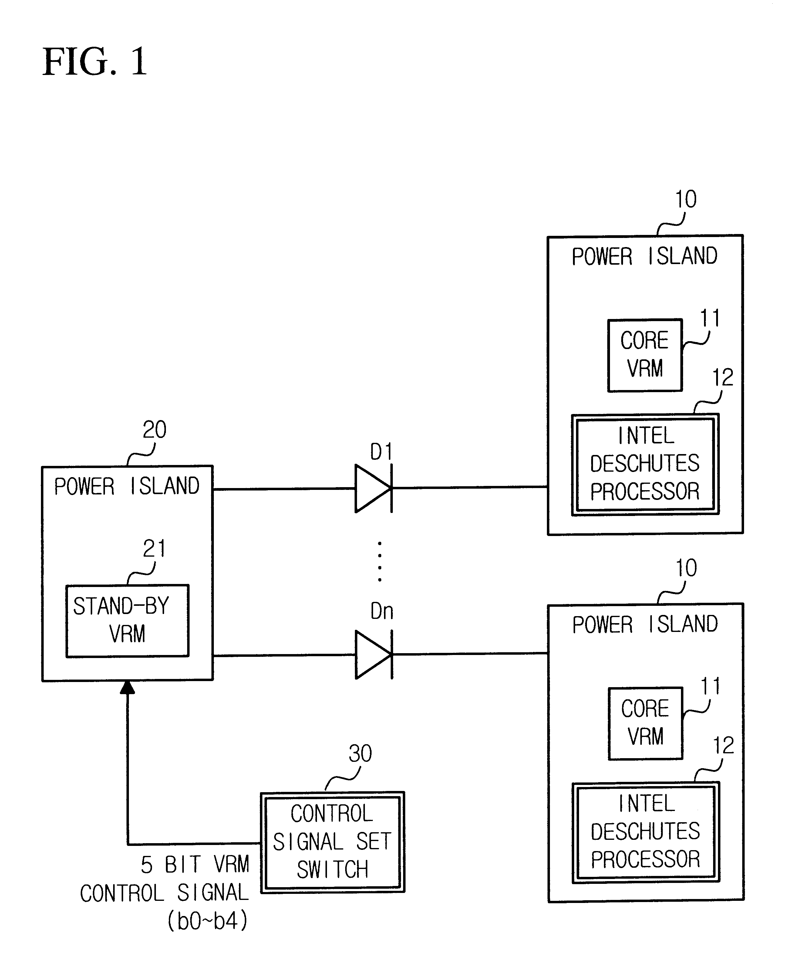
In an INTEL processor, for example, embodying the present invention, a stand-by VRM voltage is set to be as low as diode voltage drop value rather than the main VRM voltage and the stand-by VRM output voltage is programmed by a pull-up resistor or dip switch. When the main VRMs (10) (40) supply a relatively low voltage or are down, a forward bias turn-on occurs in a diode and the high programmed stand-by VRM (20) supplies power to the processor.

Additionally, one stand-by VRM (20) is coupled through a plurality of diodes (D1 and D2) to a plurality of main voltage regulator modules (10) (40), so that the stand-by VRM can back up it in the event that just one of a plurality of main VRMs fails or is down.

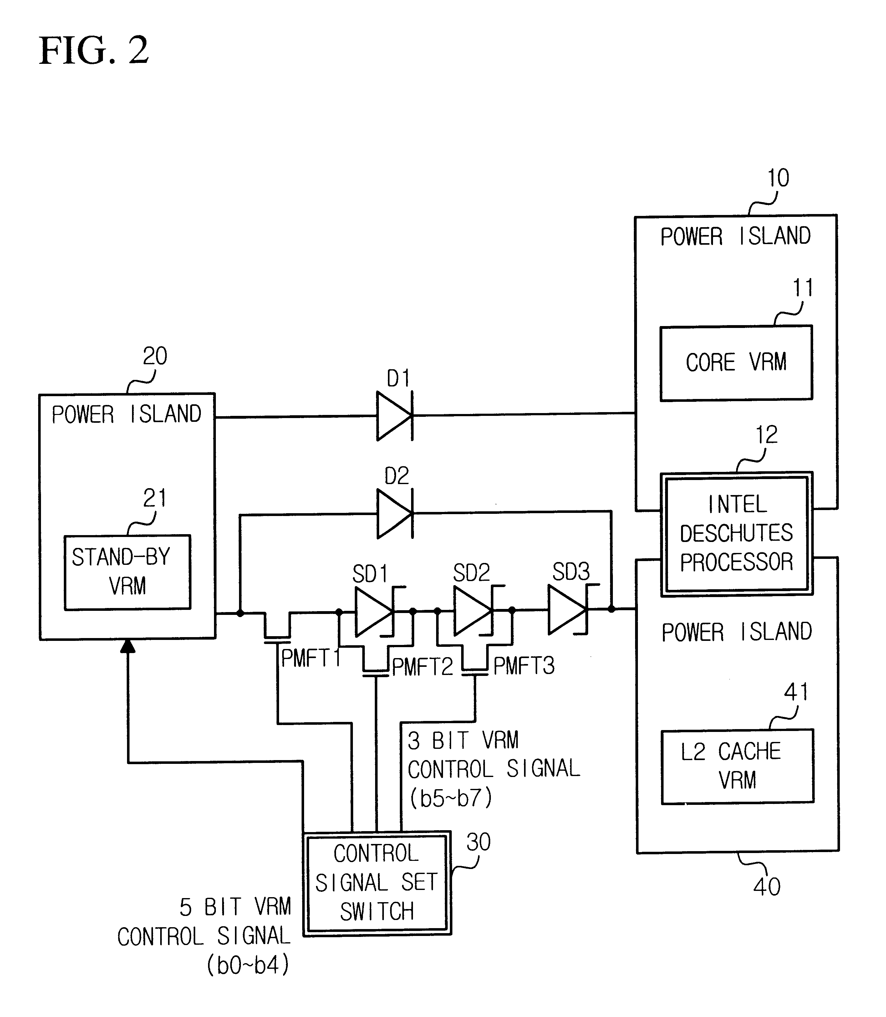
FIG. 1 illustrates a fault tolerant VRM circuit diagram for providing core power for two INTEL Deschutes processors, for example, at the same time. A stand-by VRM (12) programs output voltage by using a 5 bi...


PUM


Abstract

A fault tolerant voltage regulator module (VRM) circuit for a processor simultaneously supplies a core voltage to a plurality of processors, has a plurality of main VRMs (VRM) for supplying the same core voltage to the plurality of processors, a stand-by VRM for use upon a fault occurring in the plurality of main VRMs, a plurality of diodes connected in parallel between each of the main VRMs and the stand-by VRM for automatically supplying power to the stand-by VRM, a plurality of first power islands for connecting each of the plurality of main VRMs to the processor and each of output port of the plurality of diodes, a control signal set switch for setting output voltage level of the stand-by VRM and a second power island for connecting the stand-by VRM to input ports of the plurality of diodes and the control signal set switch. When a processor core voltage level and L2 cache voltage level are different, a fault tolerant VRM circuit further has a plurality of schottky diodes and a plurality of power MOSFETs for by-passing the schottky diodes so that the stand-by VRM can support two different voltage levels. The circuit improves stability of supplying board power owing to a fault tolerant VRM in processors and enables just one stand-by VRM to effect simultaneous support of a plurality of main VRMs and even different voltage level main VRMs using schottky diodes.

Description

CLAIM OF PRIORITYThis application makes reference to, incorporates the same herein, and claims all benefits accruing under 35 U.S.C. .sctn.119 from an application for A FAULT TOLERANT VOLTAGE REGULATOR MODULE CIRCUIT FOR SUPPLYING CORE VOLTAGE AND CACHE VOLTAGE TO INTEL PROCESSOR earlier filed in the Korean Industr Property Office on Dec. 29, 1997 and there duly assigned Ser. No. 76539 / 1997.1. Filed of the InventionThis invention relates to a voltage regulator module (VRM) circuit for a processor and in particular to a VRM circuit having a fault tolerant stand-by voltage regulator module for supplying power to a processor in the event that main VRMs fail. The stand-by VRM is coupled through diodes to the main VRMs.2. Description of the Related ArtAn earlier voltage regulator module for a processor will be explained as follows. The earlier processor converts +12 volts or +5 volts to comply with the processor using a VRM and provides a CPU core voltage and L2 cache voltage.Processors ...

Claims


Application Information

Patent Timeline
IPC IPC(8): G06F1/26G06F1/28H02J9/06H02J1/00G06F1/32
CPCG06F1/26G06F1/28H02J9/061Y04S20/20Y02B70/30G06F1/32
Inventor KIM, HYUNG-SUNLEE, IN-HOSON, HO-KYULEE, MYUNG-WOOWEON, JONG-CHELYOO, SEUNG-WHA
Owner HANGER SOLUTIONS LLC
Why Eureka
Try Eureka