Fuel filter

a technology of fuel filter and filter body, which is applied in the direction of filtration separation, machine/engine, separation process, etc., can solve the problems of relatively high environmental impact of cartridges, and achieve the effect of limited cos

Inactive Publication Date: 2011-04-21
UFI INNOVATION CENT
View PDF4 Cites 23 Cited by
  • Summary
  • Abstract
  • Description
  • Claims
  • Application Information

AI Technical Summary

Benefits of technology

[0011]The aim of the present invention is to obviate these limitations o

Problems solved by technology

The hydrophobic mesh and the filter screen are frequently made from different materials which cannot be disposed of in the same procedure, resu

Method used


Image

  • Fuel filter
  • Fuel filter
  • Fuel filter

Examples


Embodiment Construction

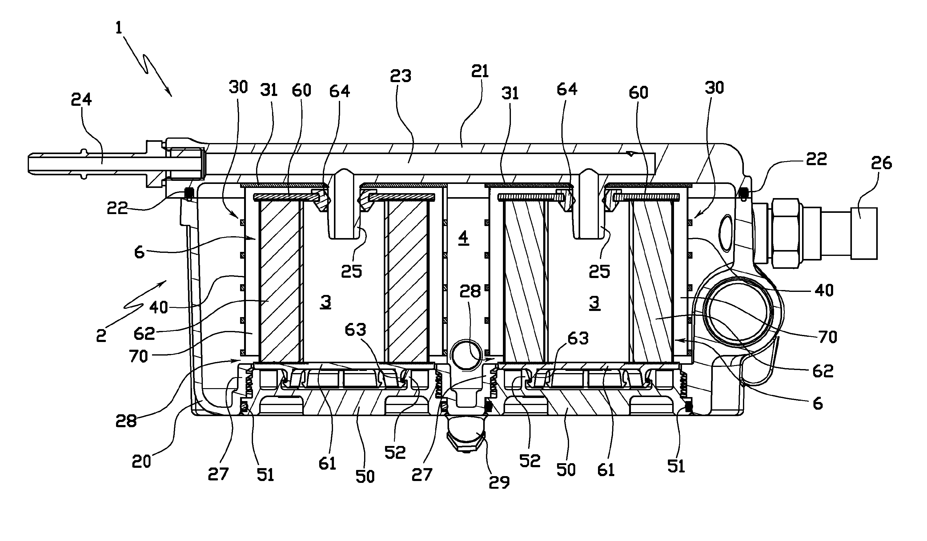
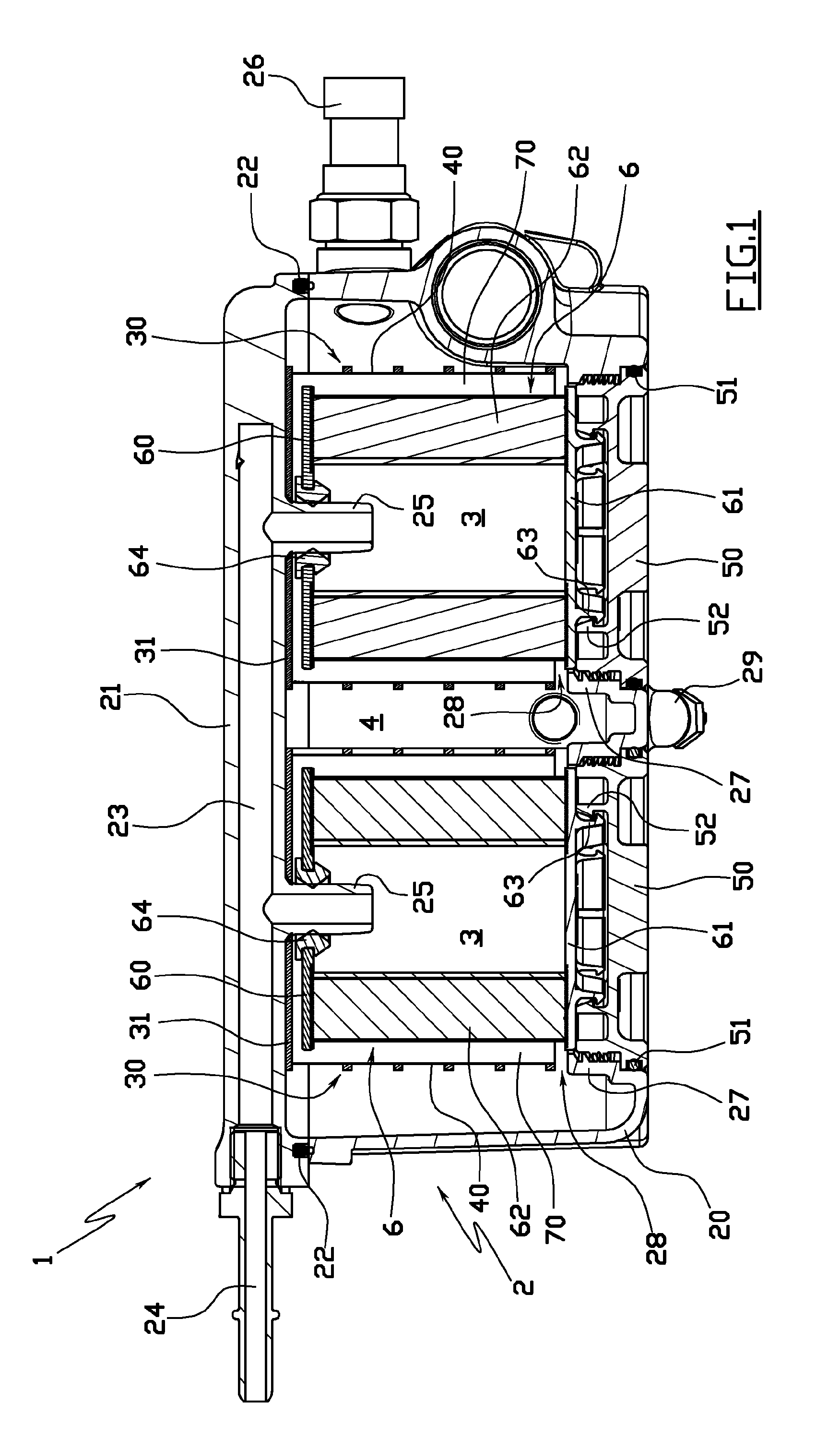
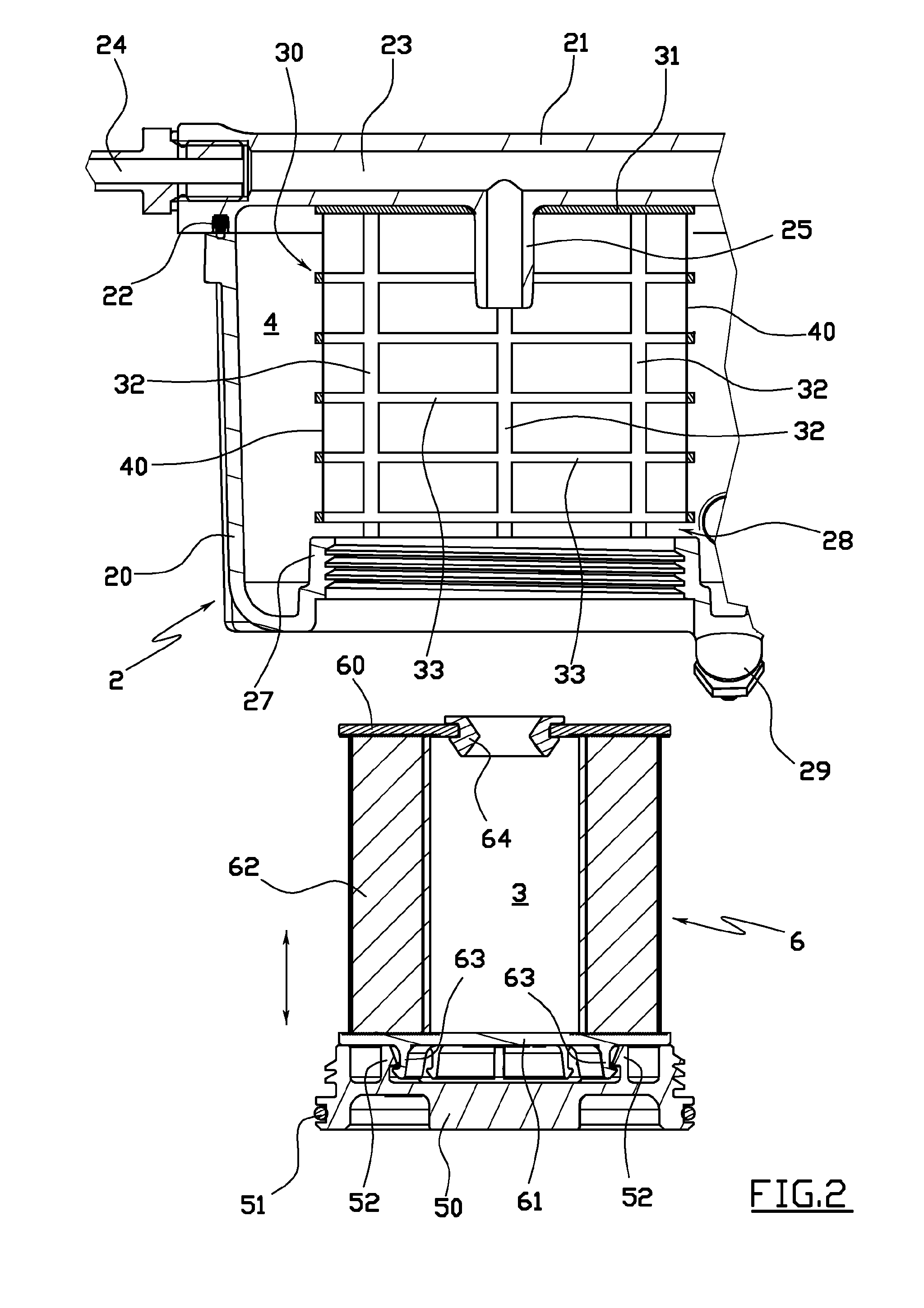
[0023]The filter 1 comprises a closed casing 2 comprising a lower element 20, shaped substantially as a dish, and an upper cover 21 flat in shape and hermetically closing the lower element 20 by way of the interpositioning of a sealing element 22.

[0024]Afforded within the upper cover 21 is a duct 23 connected to the inside of the filter through an inlet 24 for the Diesel fuel to be filtered, and connected to the internal volume of the casing 2 through two distinct projecting inlet ducts 25.

[0025]The internal volume of the casing 2 is also connected to the outside through an outlet duct 26 for the filtered Diesel fuel, passing through the side wall of the lower element 20.

[0026]Located on the bottom of the lower element 20 are two hatches 27, both located coaxially below a respective inlet duct 25 and delimited by a cylindrical side wall extending a short distance inside the casing 2.

[0027]The casing 2 contains two cage elements 30, essentially cylindrical in shape, each coaxially po...


PUM

PropertyMeasurementUnit
Volumeaaaaaaaaaa
Hydrophobicityaaaaaaaaaa

Abstract

A fuel filter, in particular for Diesel engine fuel, comprising a closed casing, the internal volume of which comprises at least a first chamber, connected to an inlet for the fuel to be filtered, and a second chamber connected to an outlet for the filtered fuel. A filter screen and a hydrophobic mesh are positioned between the first chamber and the second chamber, and the filter screen is removably fitted to the filter, independently of the hydrophobic mesh.

Description

TECHNICAL FIELD[0001]The present invention relates to a fuel filter intended for use with internal combustion engines and more specifically Diesel engines.BACKGROUND ART[0002]In many fuel supply circuits, and in particular for Diesel fuel, it is necessary to provide means for separating water from the fuel to prevent the water reaching the high pressure pump.[0003]The prior art includes various filters that separate water from fuel.[0004]A first type of filters comprise a depth type screen in a polymer material that induces coalescence of water and the descent of the water downstream of the screen relative to the direction of filtration. A second type of filter comprises a hydrophobic mesh, located in series with a normal filter screen in the filtration direction, which separates water from the fuel by coalescence.[0005]In recent times there has been an increase in the use of fuels from renewable sources, also known as “biodiesel”. Fuels of this type normally contain a quantity of w...

Claims


Application Information

Patent Timeline
IPC IPC(8): B01D35/30F02M37/24F02M37/42
CPCB01D29/21B01D36/003B01D2201/304B01D2201/305F02M37/221B01D29/52B01D29/58F02M37/24F02M37/42
Inventor GIRONDI, GIORGIO
Owner UFI INNOVATION CENT
Why Eureka
Try Eureka