Switching Voltage Regulator

a voltage regulator and switching voltage technology, applied in the direction of power conversion systems, instruments, dc-dc conversion, etc., can solve the problem of high manufacturing cos

Active Publication Date: 2011-04-21
ANPEC ELECTRONICS CORPORATION
View PDF3 Cites 44 Cited by
  • Summary
  • Abstract
  • Description
  • Claims
  • Application Information

AI Technical Summary

Problems solved by technology

To do so, the second comparator 132 has to be implemented by larger circuit layout area and operate at a slower speed as compared to other components in the switching regulator 10, leading to a higher manufacturing cost.

Method used


Image

  • Switching Voltage Regulator
  • Switching Voltage Regulator
  • Switching Voltage Regulator

Examples


Embodiment Construction

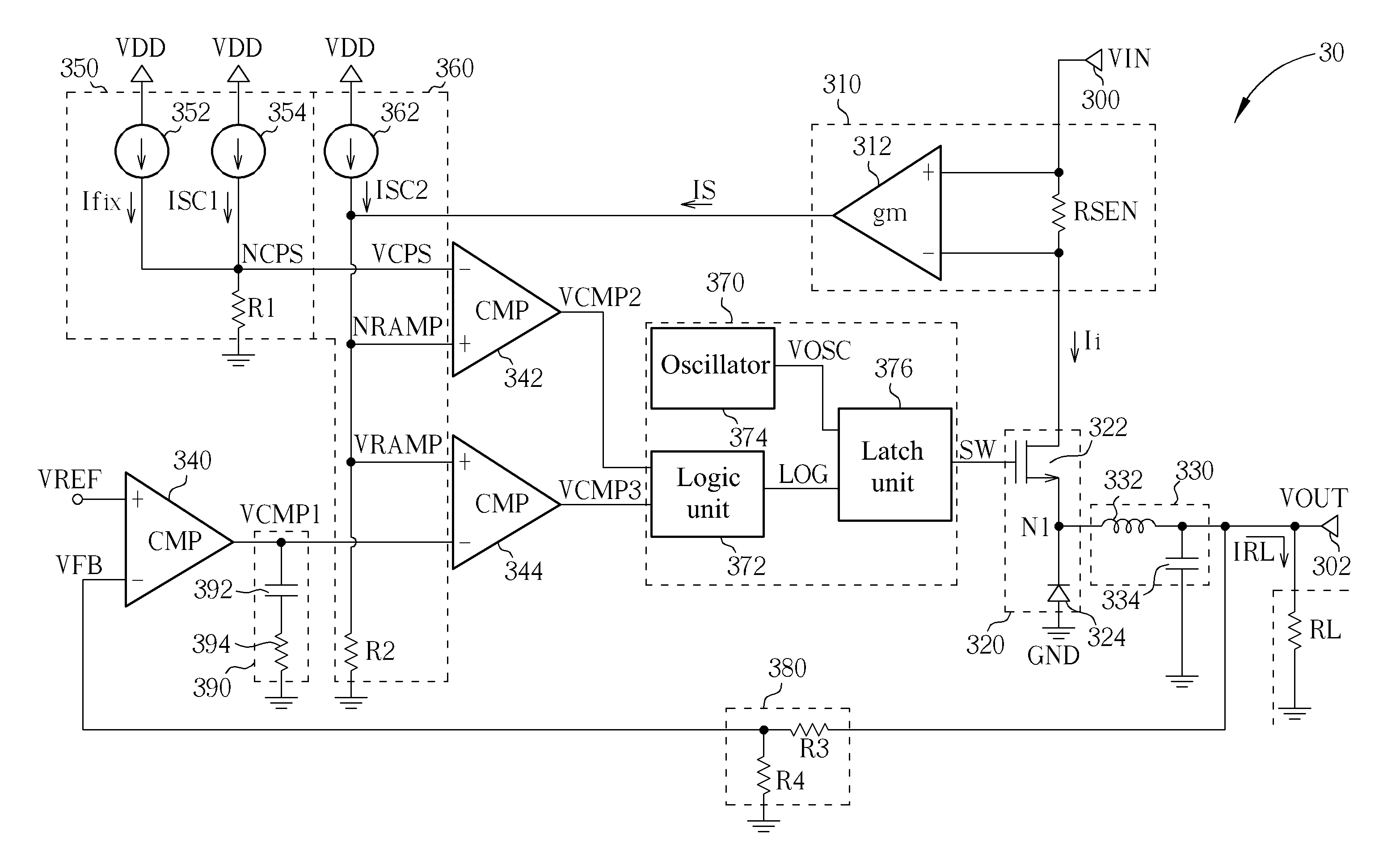
[0021]Please refer to FIG. 3, which is a schematic diagram of a switching regulator 30 according to an embodiment of the present invention. The switching regulator 30 includes an input end 300, an output end 302, a sensing module 310, a switch module 320, an output module 330, a first comparator 340, a compensation module 350, a sawtooth wave generator 360, a second comparator 342, a third comparator 344, a logic module 370 and a feedback module 380. The input end 300 is utilized for receiving an input voltage VIN from an external voltage source. The output end 302 is utilized for outputting an output voltage VOUT to a load RL. The sensing module 310 is utilized for sensing an input current Ii of the switching regulator 30 to generate a sensing current IS. The switch module 320 is utilized for determining whether the input end 300 is electrically connected to the output end 302. The output module 330 is utilized for generating the output voltage VOUT. The first comparator 340 is uti...


PUM


Abstract

A switching regulator comprises a sensing module for sensing an input current of the switching regulator to generate a sensing current, a switch module for determining whether an input end is electrically connected to an output end, a first comparator for comparing a feedback signal and a reference voltage to generate a first comparison result, a compensation module for providing a compensation signal, a sawtooth wave generator for generating a sawtooth wave signal according to the sensing current, a second comparator for comparing the sawtooth wave signal and the compensation signal to generate a second comparison result, a third comparator for comparing the sawtooth wave signal and the first comparison result to generate a third comparison result, and a logic module for generating a switching signal according to the second and the third comparison results.

Description

BACKGROUND OF THE INVENTION[0001]1. Field of the Invention[0002]The present invention is related to a switching voltage regulator, and more particularly, to a switching voltage regulator capable of fixing a floating threshold of a load current.[0003]2. Description of the Prior Art[0004]In order to prevent disturbances induced by a voltage source from influencing an electronic device, circuit designers usually install voltage regulators between the voltage source and the electronic device, to stabilize a voltage supplied by the voltage source, so as to output the voltage at a level conforming to a designated level for the electronic device. In general, voltage regulators can be divided into two categories: linear and switching. A linear regulator stabilizes its output voltage by controlling a current between a voltage source and a load. Accordingly, in a switching regulator, a current between a voltage source and a load is not continuous but composed by discrete current impulses. To ...

Claims


Application Information

Patent Timeline
Patent Type & Authority Applications(United States)
IPC IPC(8): G05F1/10
CPCH02M3/157H02M3/156
Inventor CHANG, SHAO-TE
Owner ANPEC ELECTRONICS CORPORATION
Why Eureka
Try Eureka