Video display system, video display method and display apparatus

a video display system and video display technology, applied in the direction of electrical devices, instruments, optics, etc., can solve the problems of reducing the time for displaying the video in all the lines, generating luminance unevenness in the upper and lower sides of the video display unit, and reducing the time for displaying the video. to achieve the effect of suppressing luminance unevenness

Active Publication Date: 2011-04-21
JOLED INC
View PDF9 Cites 25 Cited by
  • Summary
  • Abstract
  • Description
  • Claims
  • Application Information

AI Technical Summary

Benefits of technology

[0014]According to the video display system, the video display method, and the display apparatus according to the presen...

Problems solved by technology

However, in the conventional method described above, the following problem has been caused.
Thus, there is a conventional problem of luminance unevenness generated in the upper and lower sides of the video display unit due to the response time in switching the shutters.
In addition, as shown in FIG. 20, there ...

Method used


Image

  • Video display system, video display method and display apparatus
  • Video display system, video display method and display apparatus
  • Video display system, video display method and display apparatus

Examples


first embodiment

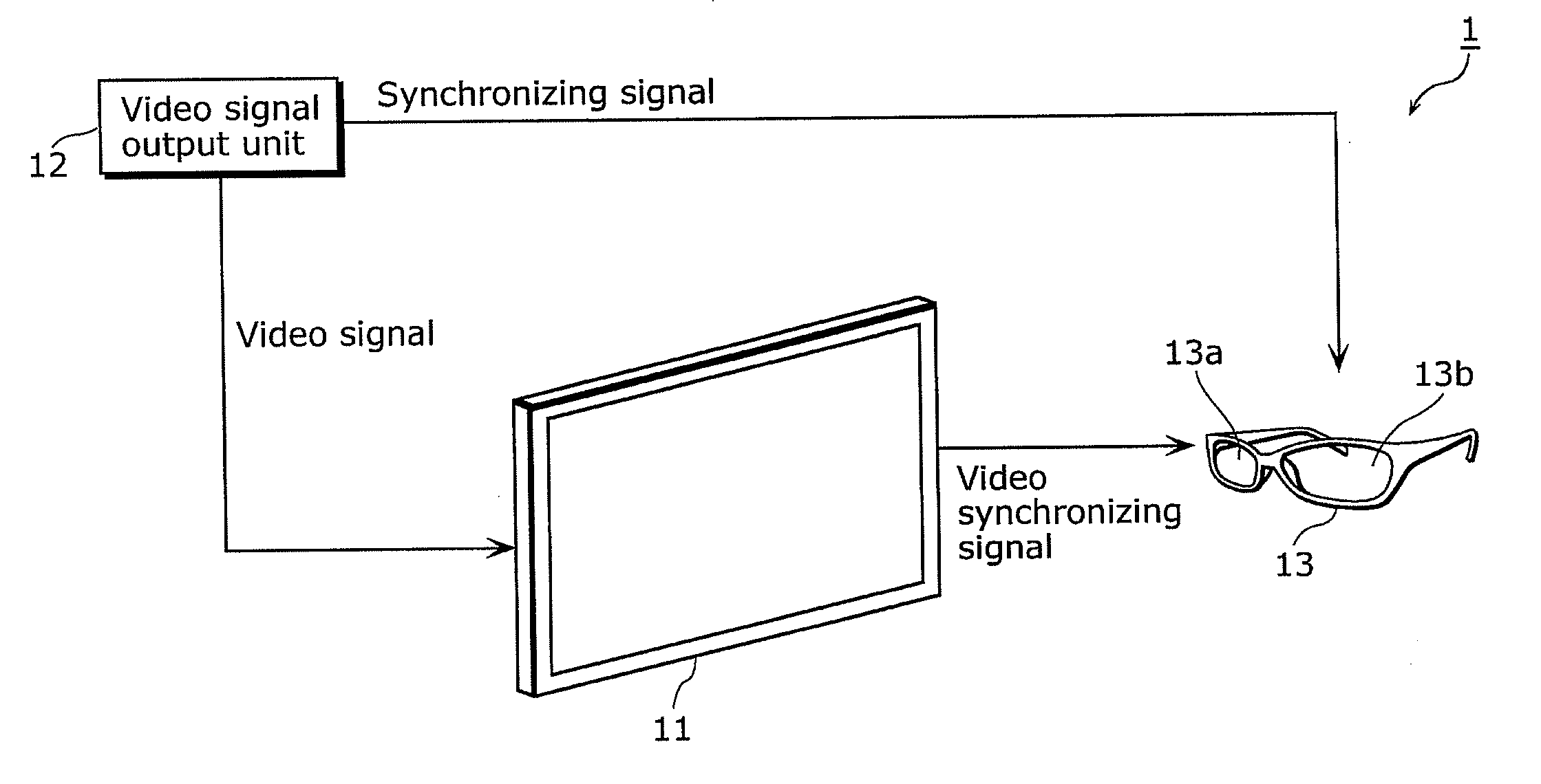
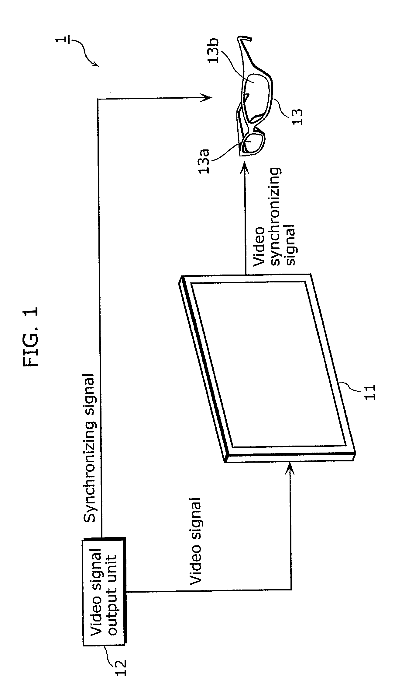
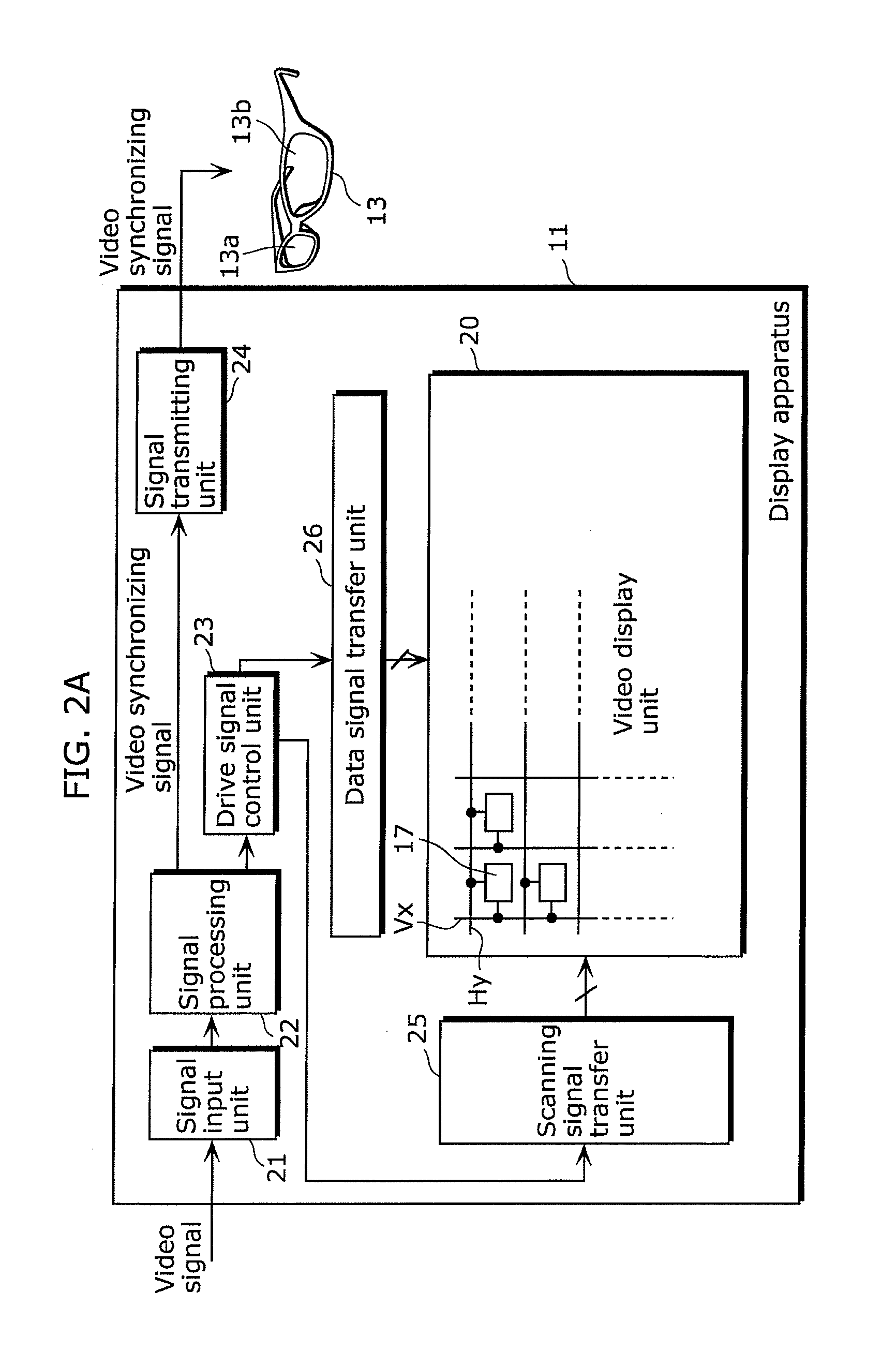
[0096]A video display system according to a first embodiment is a video display system including a display apparatus and a glasses unit with electronic shutters, and the display apparatus includes: a display unit in which pixel units are arranged in units of lines; a scanning line drive circuit which supplies a scanning signal for driving the pixel units, to each of the pixel units; a data line drive circuit which supplies a video signal to each of the pixel units arranged in the display unit; a first control unit which supplies, to the data line drive circuit, a video signal of a stereoscopic image of a picture made up of a first frame with which image information for one eye is set and a second frame with which image information for the other eye is set, the image information for one eye and the image information for the other eye corresponding to a same picture of stereoscopic video; and a first communication unit which transmits, to the glasses unit with electronic shutters, a v...

second embodiment

[0153]Next, a video display system according to a second embodiment of the present invention is described.

[0154]The present embodiment differs from the first embodiment only in that the black signal is supplied only during a shutter closing period in which both the right eye shutter 13a and the left eye shutter 13b are closed.

[0155]FIG. 11A is a diagram showing display video that is recognized by the viewer with the right eye, left eye, and both eyes, respectively, when opening and closing the right eye shutter 13a and the left eye shutter 13b of the glasses unit with electronic shutters 13 according to the present embodiment.

[0156]As shown in FIG. 11A, due to the response time in opening and closing of the shutters, the shutter closing period in which both of the shutters are closed is provided while the video synchronizing signal is switching the opening and closing of the shutters from the right eye shutter 13a to the left eye shutter 13b, or while switching the opening and closi...


PUM


Abstract

A video display apparatus includes pixels arranged in lines, a scanning signal transferor that supplies scanning signals to the pixels, and a data signal transferor that supplies a video signal to the pixels. A first controller supplies the video signal to the data signal transferor and causes the scanning signal transferor to supply a first scanning signal that corresponds to a first picture to the lines in the display from a head line to a final line and a second scanning signal that corresponds to a second picture subsequent to the first picture to the lines in the display from the final line to the head line.

Description

CROSS REFERENCE TO RELATED APPLICATION[0001]This is a continuation application of PCT Application No. PCT / JP2009 / 005436, filed on Oct. 19, 2009, designating the United States of America, the disclosure of which, including the specification, drawings, and claims, is incorporated herein by reference in its entirety.BACKGROUND OF THE INVENTION[0002]1. Field of the Invention[0003]The present invention relates to a video display system, a video display method, and a display apparatus which are configured to be adapted to displaying stereoscopic video.[0004]2. Description of the Related Art[0005]Conventionally, various schemes have been considered to display stereoscopic video. As an example, there is a method for generating stereoscopic video by alternately displaying image information for one eye and image information for the other eye which create a disparity for visually recognizing the stereoscopic video, and by switching shutters of glasses with electronic shutters (For example, see...

Claims


Application Information

Patent Timeline
IPC IPC(8): H04N13/04
CPCG02B27/2264H04N13/0438H04N13/0497G09G2320/0252G09G3/3233G09G2310/061G09G3/003G02B30/24H04N13/341H04N13/398
Inventor TSUCHIDA, SHINYA
Owner JOLED INC
Why Eureka
Try Eureka