Constant velocity universal joint

a constant velocity, universal joint technology, applied in the direction of couplings, yielding couplings, couplings, etc., can solve the problems of reducing the durability of the boot, abrasion on the inner surface of the boot, etc., to suppress the abrasion of the boot, compact and enhanced durability

Active Publication Date: 2011-04-21
NTN CORP
View PDF3 Cites 3 Cited by
  • Summary
  • Abstract
  • Description
  • Claims
  • Application Information

AI Technical Summary

Benefits of technology

[0031]According to the present invention, it is possible to provide a constant velocity universal joint in whic

Problems solved by technology

Owing to the contact, abrasion may occur on the inner surfaces of the boot.
The abra

Method used


Image

  • Constant velocity universal joint
  • Constant velocity universal joint
  • Constant velocity universal joint

Examples


example 1

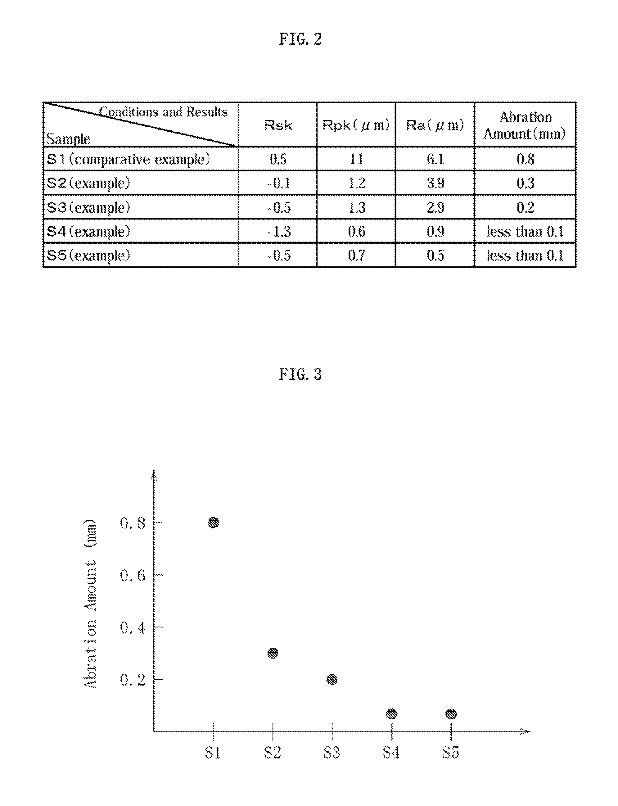
[0040]An evaluation test of an abrasion amount of a boot was conducted under the following conditions. operational angle: 40°, number of rotations: 600 rpm, ambient temperature: 25° C.

[0041]FIG. 2 shows conditions of surface roughness of the outer peripheral surface of the shaft used. Note that, S5 was manufactured by subjecting S1 to powder coating, and surface roughness of S5 described above is that of the surface of the coating film formed by painting. All the boots and the constant velocity universal joints except the shafts are of the same specifications.

[0042]Rightmost columns of FIG. 2 show abrasion amounts of the inner surfaces of the valley portions of the boots of S1 to S5 after an operation for a predetermined period of time. FIG. 3 shows a relation among the abrasion amounts of S1 to S5. As apparent from FIG. 3, the relation among the abrasion amounts of S1 to S5 were as follows.

S1>>S2>S3>S4≈S5

[0043]This result confirms the following. The abrasion amounts of S4 and S5 wh...


PUM


Abstract

Provided is a constant velocity universal joint in which a boot can be enhanced in durability and compactified, which are achieved by suppressing abrasion of the boot. In the constant velocity universal joint including: an outer joint member (1); an inner joint member (2); a torque transmitting member (3); a shaft (5); and a hoot (6), surface roughness of an outer peripheral. surface (5a) of the shaft (5) satisfies Rsk<0, Rpk<2 μm, and Ra<4 μm.

Description

TECHNICAL FIELD[0001]The present invention relates to a constant velocity universal joint used, for example, for a drive shaft of an automobile.[0002]Constant velocity universal joints are roughly classified into fixed type joints which solely allow angular displacement between input and output shafts and slide type joints in which angular displacement and axial displacement are permissible, and the kind of the joint to be used is selected according to its application, condition of use, etc.[0003]In a constant velocity universal joint of any of a fixed type and a Plunging type, an outer joint member, an inner joint member, a torque transmitting member, a shaft, and a boot are provided as main components. The outer joint member has a cup-shaped member opened at one end. The inner joint member is located in inside of the cup-shaped part. The torque transmitting members transmit torque between the outer joint member and the inner joint member. The shaft is coupled with the inner joint ...

Claims


Application Information

Patent Timeline
IPC IPC(8): F16D3/04F16D3/84
CPCF16J3/043F16D3/845F16D3/223F16D2300/10
Inventor TAKABE, SHINICHI
Owner NTN CORP
Why Eureka
Try Eureka