System and apparatus for see-through display panels

a technology of see-through display and apparatus, applied in the field of optics, can solve the problems of unattractive solutions for some applications, unsuitable for applications, and large system size, and achieve the effect of reducing the number of devices

Active Publication Date: 2011-04-28
INNOVEGA
View PDF49 Cites 210 Cited by
  • Summary
  • Abstract
  • Description
  • Claims
  • Application Information

AI Technical Summary

Benefits of technology

[0009]According to an additional embodiment, a display system is provided, comprising: a display assembly disposed on a head-borne apparatus, wherein the display assembly is positioned in close proximity to an eye of a viewer such that the eye is unable to focus on the display assembly unassisted, and the display assembly comprises a transparent display panel having pixels configured without focusing optics, thereby allowing light emitted by the pixels to diverge unfocused; and a contact lens having focusing optics that assists the eye in focusing on light emitted by the pixels of the transparent display panel.

Problems solved by technology

Current systems for optical processing of display information provided by a head-mounted display and non-display information provided by objects other than the head-mounted display may have characteristics that make them unattractive solutions for some applications.
Such systems tend to be large, bulky and ill suited for applications where little space is available for processing the display information and the non-display information.
For example, such systems are unattractive solutions for processing display and non-display information in a fighter pilot's helmet where the space for the optical system is limited.

Method used


Image

  • System and apparatus for see-through display panels
  • System and apparatus for see-through display panels
  • System and apparatus for see-through display panels

Examples


Embodiment Construction

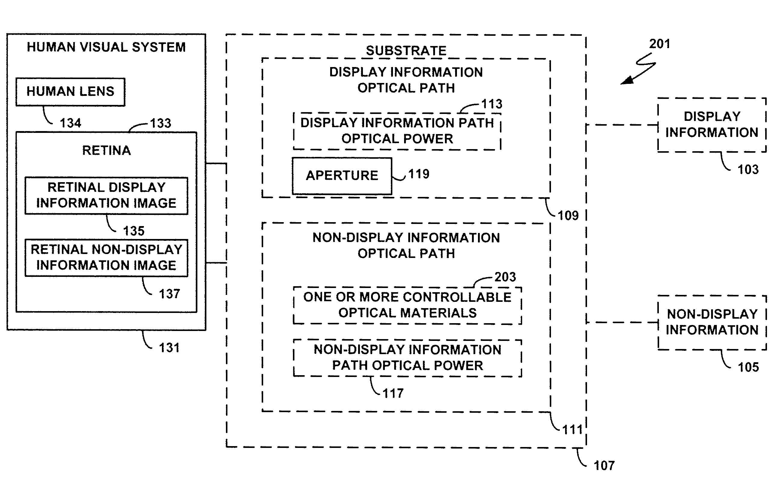
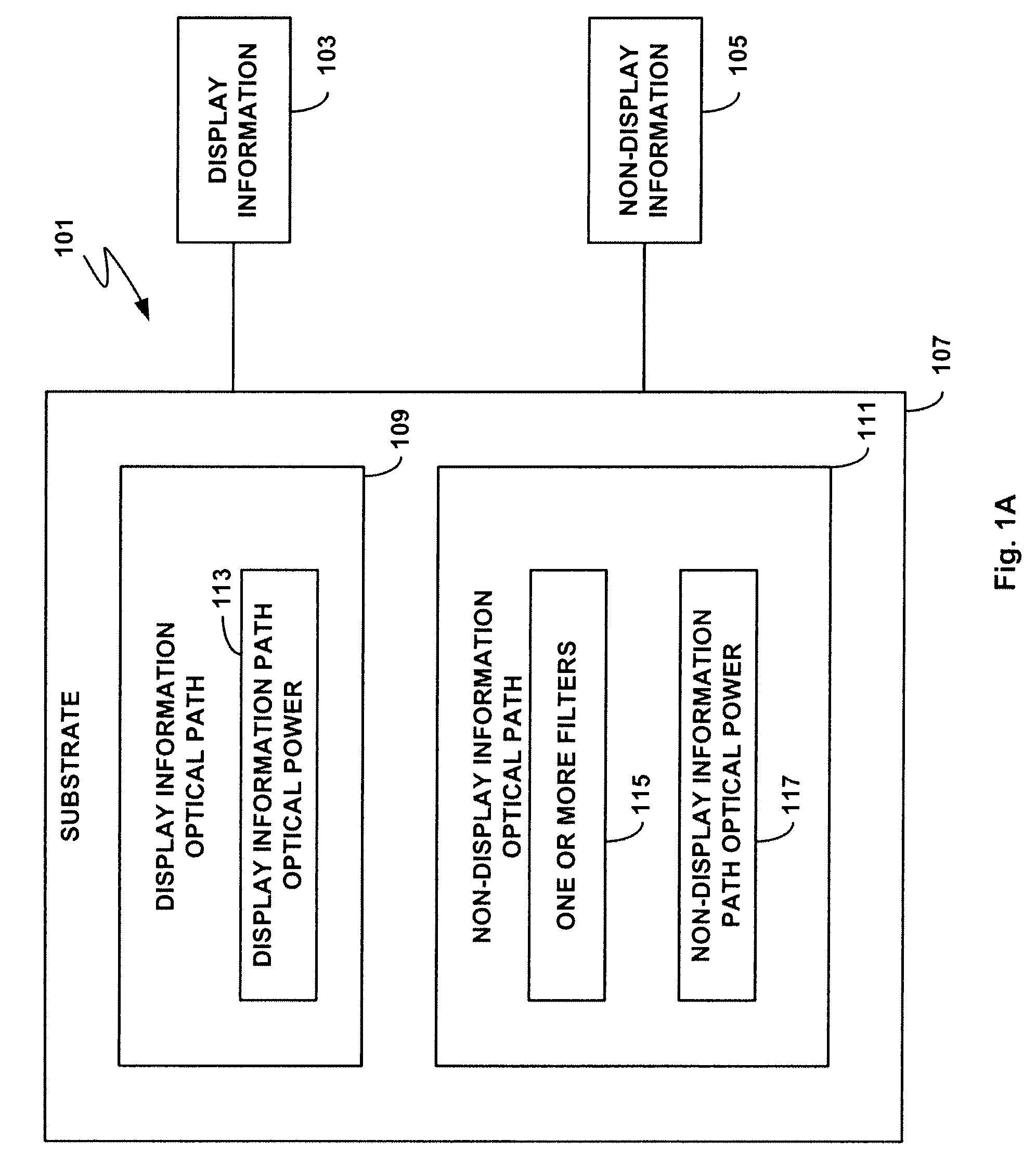
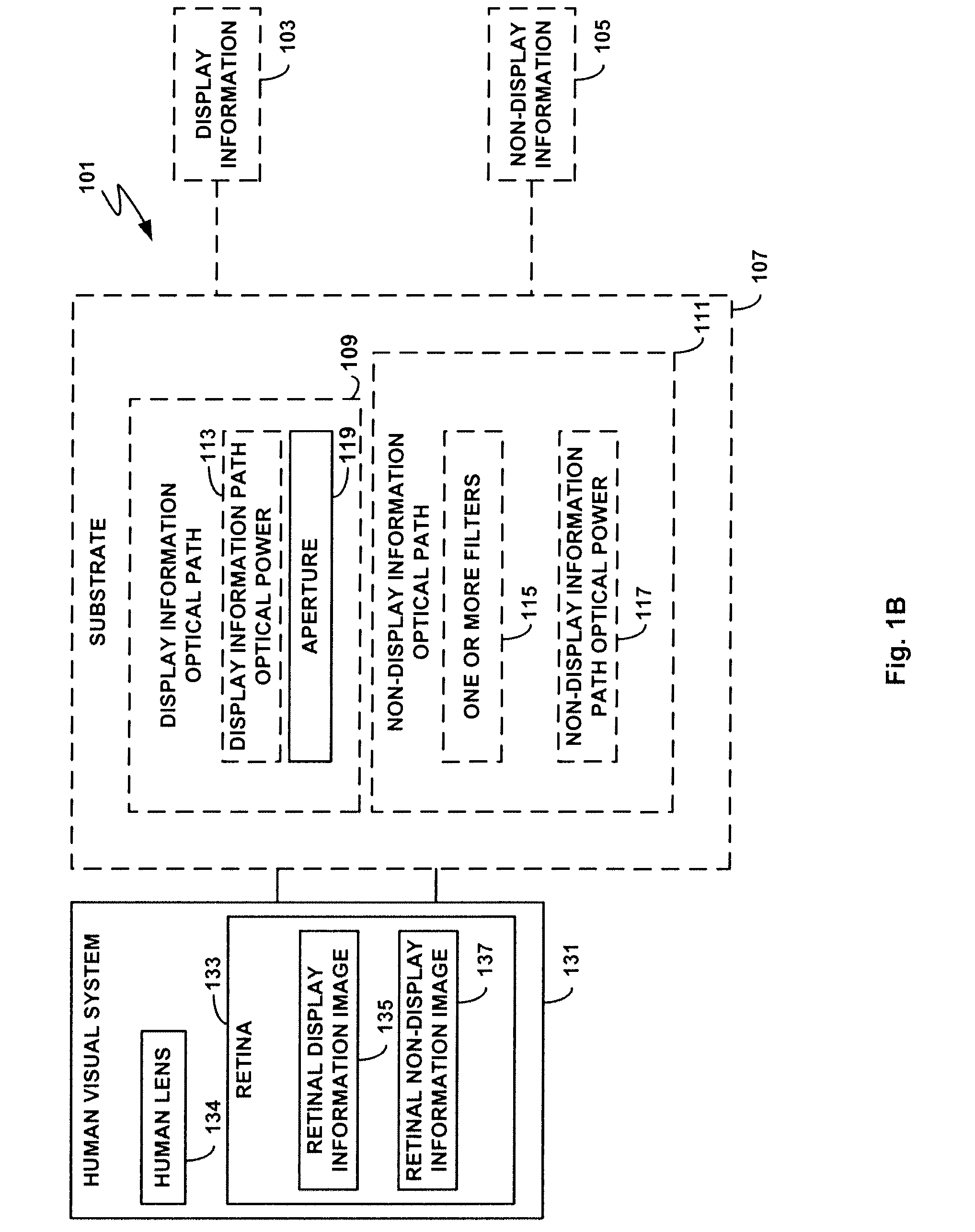
[0004]Various embodiments of the present invention provide systems and apparatus directed toward using a display panel to process display information and non-display information. Further embodiments utilize a display panel in conjunction with a contact lens assembly configured to process the display information.

[0005]In one embodiment of the invention, a display panel assembly is provided, comprising: a transparent substrate that permits light to pass through substantially undistorted; a reflector disposed on the transparent substrate; and a display panel aimed toward the reflector and substantially away from a human visual system, wherein the reflector reflects light emitted from the display panel toward the human visual system. The reflector may be a narrow band reflector or a polarization reflector. Additionally, the display panel assembly may further comprise a bandpass filter positioned adjacent to the display panel, wherein the bandpass filter limits bandwidths of light emitte...


PUM

PropertyMeasurementUnit
distanceaaaaaaaaaa
distanceaaaaaaaaaa
distanceaaaaaaaaaa

Abstract

Various embodiments of the present invention provide for systems and apparatus directed toward using a contact lens and deflection optics to process display information and non-display information. In one embodiment of the invention, a display panel assembly is provided, comprising: a transparent substrate that permits light to pass through substantially undistorted; a reflector disposed on the transparent substrate; and a display panel aimed toward the reflector and substantially away from a human visual system, wherein the reflector reflects light emitted from the display panel toward the human visual system. The reflector may comprise a narrow band reflector or a polarization reflector.

Description

RELATED APPLICATION [0001]This application is a continuation-in-part of and claims the benefit of U.S. patent application Ser. No. 12 / 204,567 filed Sep. 4, 2008, which is incorporated herein by reference in its entirety.FIELD OF THE INVENTION[0002]The present invention is related to optics and, more specifically, is directed toward optical processing of display information and non-display information using display panels and a dual path contact lens.DESCRIPTION OF THE RELATED ART[0003]Current systems for optical processing of display information provided by a head-mounted display and non-display information provided by objects other than the head-mounted display may have characteristics that make them unattractive solutions for some applications. The twin requirements of a large field of view and a comfortable eye-to-system distance for the viewer results in multi-component optical systems where the final optical component has a large diameter. Such systems tend to be large, bulky a...

Claims


Application Information

Patent Timeline
Patent Type & Authority Applications(United States)
IPC IPC(8): G09G5/10G09G5/00G02B27/01G02F1/1335
CPCG02B5/1876G02B5/20G02B5/30G02B27/0172G02C7/04G02C7/086G09G2320/0626G02C7/102G02C7/12G02C2202/20G09G3/3607G09G2300/0478G02C7/101G02B27/1006G02B27/286
Inventor SPRAGUE, RANDALL
Owner INNOVEGA
Why Eureka
Try Eureka