Power control for devices having multiple antennas

a technology of power control and antennas, applied in power management, duplex signal operation, wireless communication, etc., can solve problems such as antenna gain imbalances

Active Publication Date: 2011-04-28
INTERDIGITAL PATENT HLDG INC
View PDF15 Cites 101 Cited by
  • Summary
  • Abstract
  • Description
  • Claims
  • Application Information

AI Technical Summary

Benefits of technology

[0006]Power control methods for devices using multiple transmit antennas for transmission in the uplink (UL) are disclosed herein. Methods include changing the power of a physical uplink control channel (PUCCH) transmission to a new level, the new level depending at least in part on a multiple input multiple output (MIMO) mode (a transmission mode configuration). Another method describes changing the power of sounding reference signal (SRS) transmission to a new level, the new level depending at least in part on a selected MIMO mode (or a transmission mode configuration). A method is provided to estimate an antenna gain imbalance (AGI) for transmit antennas based on measured Reference Signal Received Power (RSRPs) and each transmit antenna is scaled by an AGI scaling factor that is based on the estimated AGIs. The estimated AGIs may be expressed in terms of scaled relative AGIs with regard to a reference transmit antenna.

Problems solved by technology

An antenna gain imbalance (AGI) may occur when using multiple antenna transmissions in the UL.

Method used


Image

  • Power control for devices having multiple antennas
  • Power control for devices having multiple antennas
  • Power control for devices having multiple antennas

Examples


Embodiment Construction

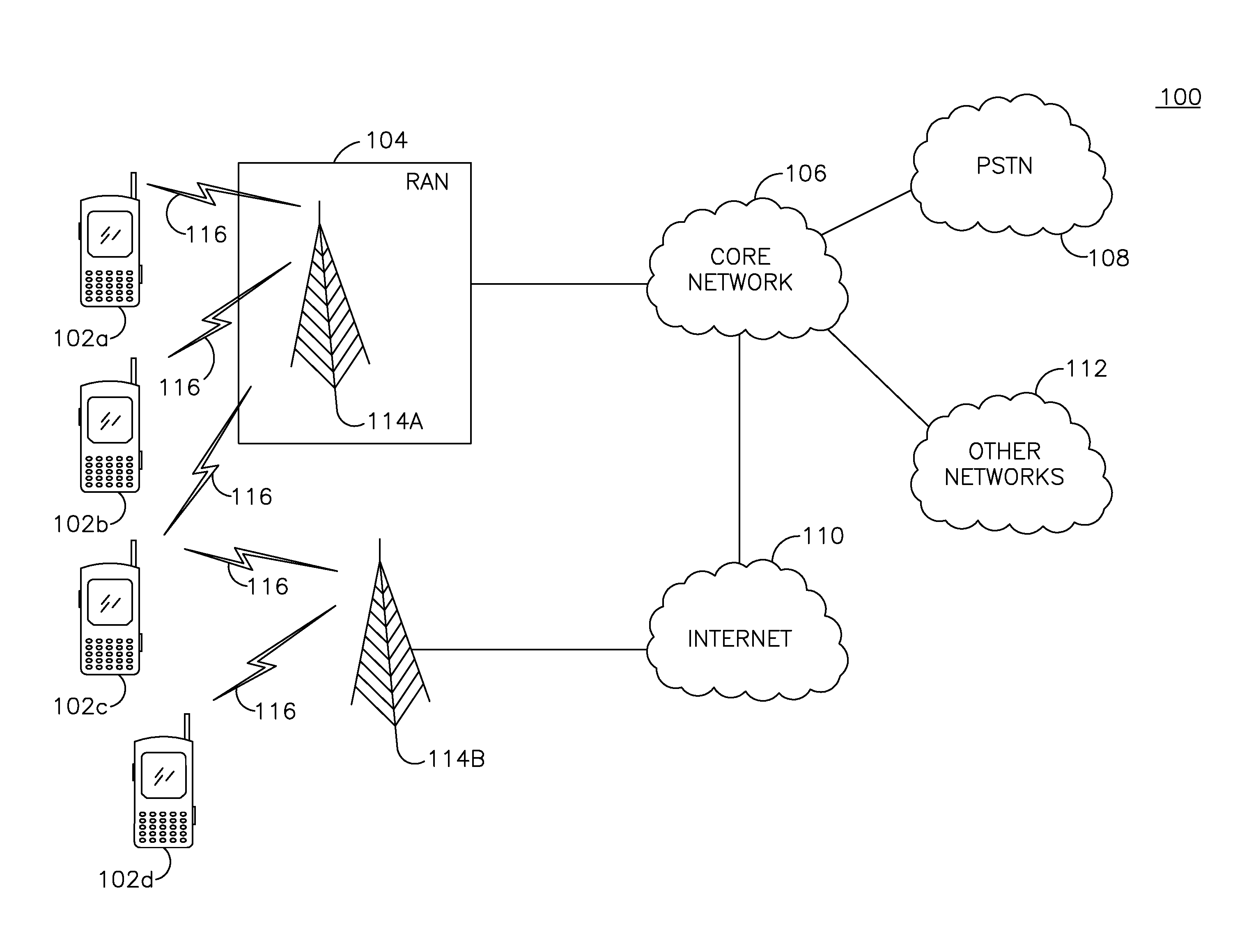
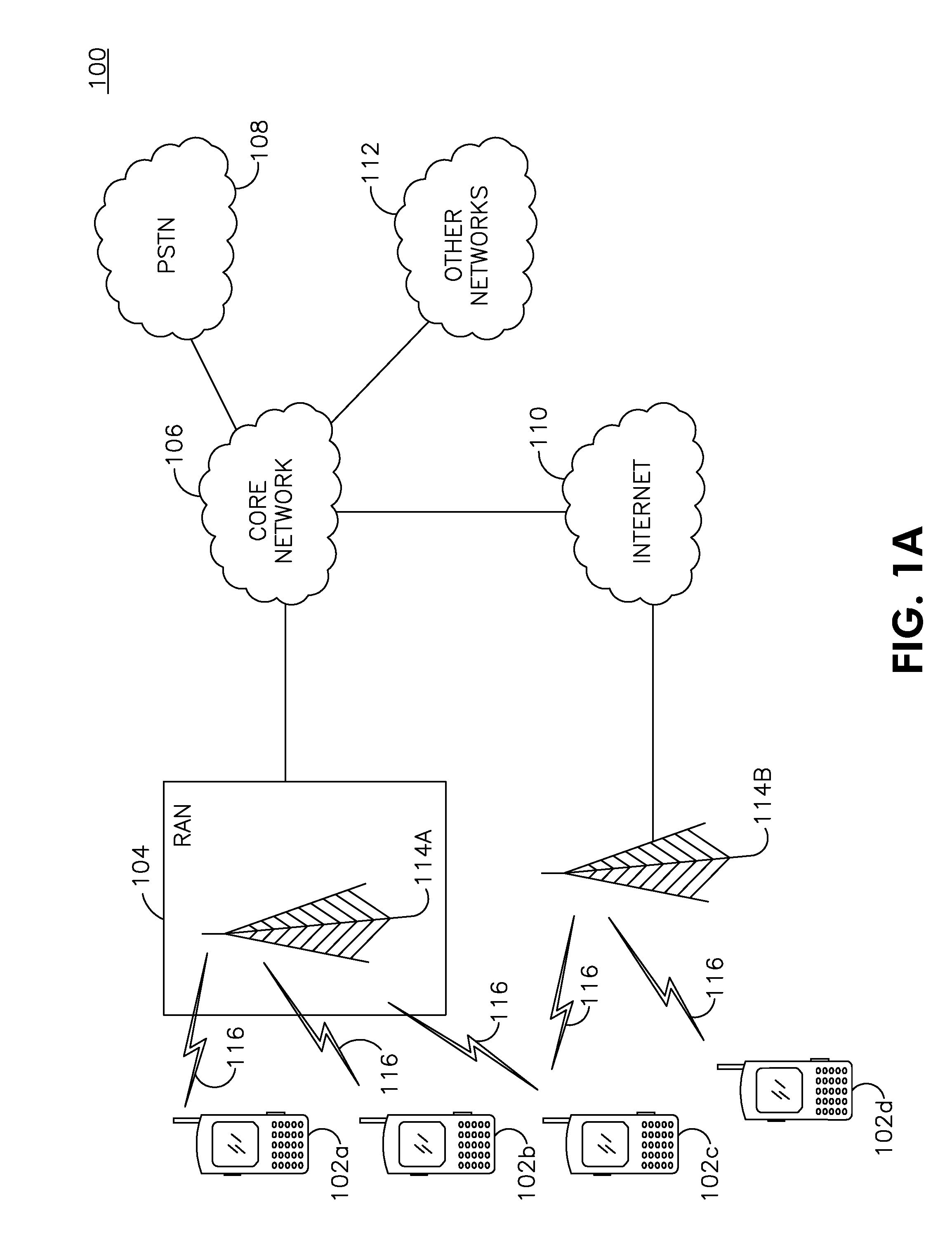
[0015]FIG. 1A is a diagram of an example communications system 100 in which one or more disclosed embodiments may be implemented. The communications system 100 may be a multiple access system that provides content, such as voice, data, video, messaging, broadcast, etc., to multiple wireless users. The communications system 100 may enable multiple wireless users to access such content through the sharing of system resources, including wireless bandwidth. For example, the communications systems 100 may employ one or more channel access methods, such as code division multiple access (CDMA), time division multiple access (TDMA), frequency division multiple access (FDMA), orthogonal FDMA (OFDMA), single-carrier FDMA (SC-FDMA), and the like.

[0016]As shown in FIG. 1A, the communications system 100 may include wireless transmit / receive units (WTRUs) 102a, 102b, 102c, 102d, a radio access network (RAN) 104, a core network 106, a public switched telephone network (PSTN) 108, the Internet 110,...


PUM


Abstract

Power control for devices having multiple transmit antennas are disclosed, including power control methods for Physical Uplink Control Channel (PUCCH) and Sounding Reference Signal (SRS) transmissions for a wireless transmit/receive unit (WTRU). The PUCCH and SRS power control methods include selecting a multiple input multiple output (MIMO) mode and changing the power of the PUCCH or SRS transmission based on the selected MIMO mode. Another power control method estimates an antenna gain imbalance (AGI) for a WTRU having at least two transmit antennas. The AGI is based on measuring a Reference Signal Received Power (RSRP) on each transmit antenna. Each transmit antenna is then scaled by an AGI scaling factor based on the estimated AGI.

Description

CROSS REFERENCE TO RELATED APPLICATION[0001]This application claims the benefit of U.S. provisional application No. 61 / 248,203 filed on Oct. 2, 2009, the contents of which are hereby incorporated by reference herein.FIELD OF THE INVENTION[0002]This application is related to wireless communications.BACKGROUND[0003]In Third Generation Partnership Project (3GPP) long term evolution (LTE) Release 8 (R8) uplink (UL), wireless transmit / receive units (WTRUs) may transmit their data (and sometimes their control information) on the physical uplink shared channel (PUSCH). The evolved Node B (eNB) may schedule and control PUSCH transmission from each WTRU using an UL scheduling grant, which may be carried on a physical downlink control channel (PDCCH) format 0. As part of the uplink scheduling grant, the WTRU may receive control information on the modulation and coding set (MCS), the transmit power control (TPC) command, uplink resource allocation (e.g., the indices of allocated resource block...

Claims


Application Information

Patent Timeline
Patent Type & Authority Applications(United States)
IPC IPC(8): H04B1/38
CPCH04B7/0689H04W52/325H04B7/0871H04W52/42H04B7/0413H04B7/0426H04L5/0053H04W52/146H04W72/21
Inventor SHIN, SUNG-HYUKSTERN-BERKOWITZ, JANET A.KOO, CHANG-SOOBELURI, MIHAELA C.
Owner INTERDIGITAL PATENT HLDG INC
Why Eureka
Try Eureka