Sound reproduction device with enhanced low-frequency sound effect

a low-frequency sound and sound effect technology, applied in the direction of transducer details, electrical transducers, electrical apparatus, etc., can solve the problems of low acoustic volume, low acoustic quality, and the user is unlikely to hear the sound loud and clear, and achieve and enhanced low-frequency sound effect

Inactive Publication Date: 2011-04-28
HU KEN PEI
View PDF3 Cites 14 Cited by
  • Summary
  • Abstract
  • Description
  • Claims
  • Application Information

AI Technical Summary

Benefits of technology

[0015]FIG. 2 is a sectional view of a first preferred embodiment of a sound reproduction device with enhanced low-frequency sound effect according to the present invention;
[0016]FIG. 3 is a sectional view of a second preferred embodiment of the sound reproduction device with enhanced low-frequency sound effect according to the present invention;
[0017]FIG. 4 is a sectional view of a third preferred embodiment of the sound reproduction device with enhanced low-frequency sound effect according to the present invention;
[0018]FIG. 5 is a sectional view of a fourth preferred embodiment of the sound reproduction device with enhanced low-frequency sound effect according to the present invention; and
[0019]FIG. 6 is a sectional view of a fifth preferred embodiment of the sound reproduction device with enhanced low-frequency sound effect according to the present invention.

Problems solved by technology

However, as stated above, with compactness being the mainstream design concept for electronic products nowadays, loudspeakers used in such electronic products tend to be small and thus only produce low acoustic volume, particularly of the low-frequency range.
In consequence, when electronic products of this kind are used to reproduce sound, it is unlikely for the user to hear the sound loud and clear, nor fully appreciate the low-frequency sound effect of the loudspeakers.
Therefore, under the current trend in electronic product design, it is a pressing problem for loudspeaker manufacturers to balance between the dimension and the quality and volume of sound of a loudspeaker, with a view to offering optimal sound reproduction effect to consumers.
1. For the sound reproduction device 1 to reproduce sound, it is necessary that both the loudspeakers 11, 12 are driven. Therefore, the sound reproduction device 1, though capable of making sound at larger volume and producing more significant low-frequency sound effect than a traditional loudspeaker, consumes twice as much power, too. In other words, the sound reproduction device 1 works against the concept of energy saving and environmental protection that the entire world today endeavors to live up to.
2. While the sound reproduction device 1 is in operation, the loudspeakers 11, 12 must sound synchronously so as for the sound reproduction device 1 to make sound properly, without noise or audio signal interference. Hence, it is imperative that the specifications, circuits, and installation locations of the loudspeakers 11, 12 be strictly planned and designed; otherwise, the loudspeakers 11, 12 in the sound reproduction device 1 may not sound synchronously. Therefore, the sound reproduction device 1 incurs considerable costs of design and quality control during the design and production processes, which makes it impossible to effectively reduce the selling price of the sound reproduction device 1. And because of that, market competitiveness of the sound reproduction device 1 may be seriously impaired.
3. In addition, since the sound reproduction device 1 requires two loudspeakers, material costs of the sound reproduction device 1 are lofty. This also contributes to the high selling price and low market competitiveness of the sound reproduction device 1.

Method used


Image

  • Sound reproduction device with enhanced low-frequency sound effect
  • Sound reproduction device with enhanced low-frequency sound effect
  • Sound reproduction device with enhanced low-frequency sound effect

Examples


Embodiment Construction

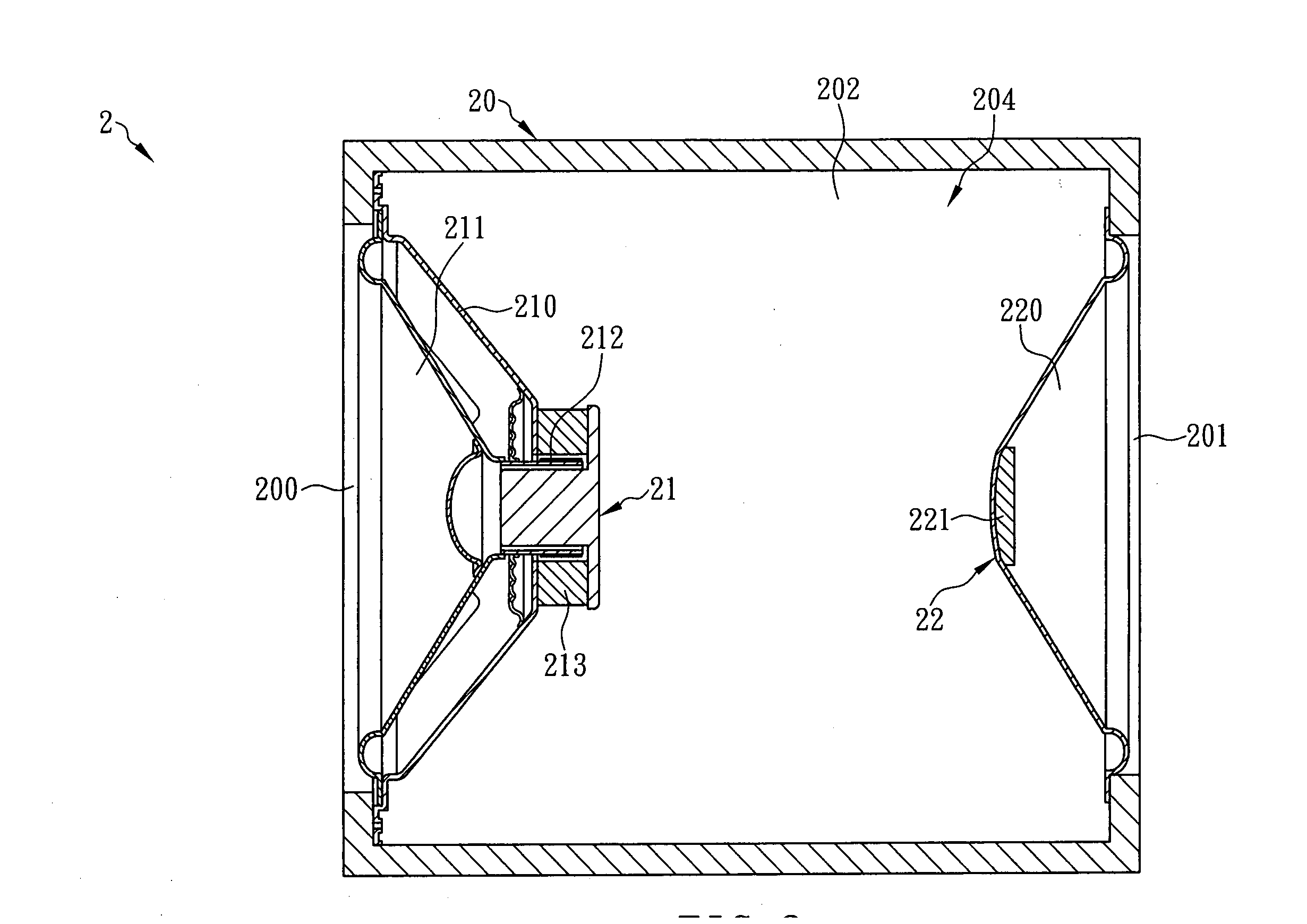
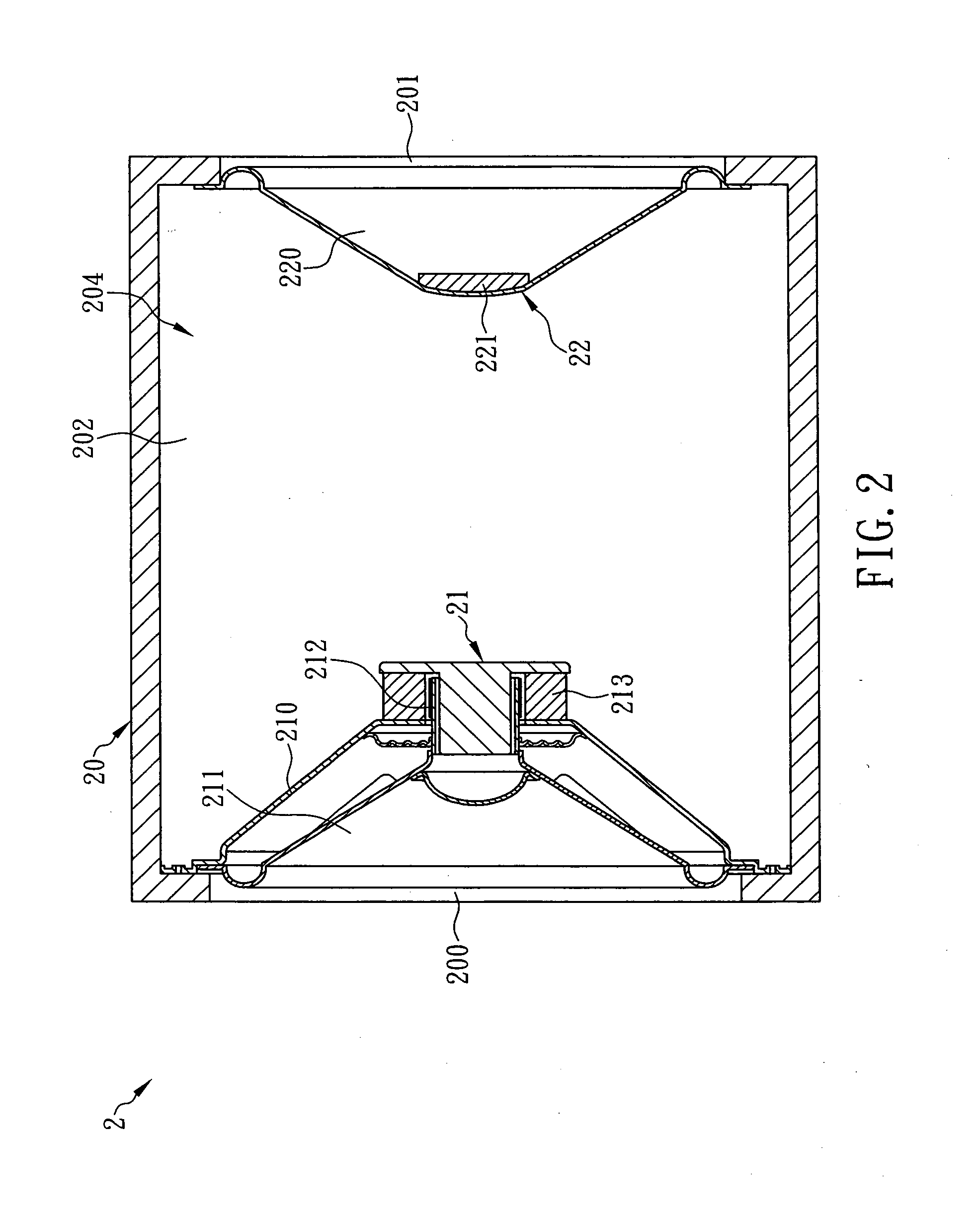
[0020]The present invention provides a sound reproduction device with enhanced low-frequency sound effect. Referring to FIG. 2, a sound reproduction device 2 according to a preferred embodiment of the present invention includes a tube 20, a loudspeaker 21, and a resonance unit 22. The tube 20 has two ends which are formed with a first opening 200 and a second opening 201, respectively. In addition, the tube 20 is provided therein with an accommodating space 204. The loudspeaker 21 includes a frame body 210, a first diaphragm 211, a coil 212, and a magnetic element 213. The first diaphragm 211 is attached to an inner periphery of a side of the frame body 210. The coil 212 is centrally provided at an inner periphery of the first diaphragm 211. The magnetic element 213 is provided at an inner periphery of an opposite side of the frame body 210 and mounted around a periphery of the coil 212. In the loudspeaker 21, the side of the frame body 210 that is adjacent to the first diaphragm 21...


PUM


Abstract

This invention is to provide a sound reproduction device including a tube, a loudspeaker and a resonance unit, wherein the loudspeaker includes a frame body having a side adjacent to a first diaphragm thereof peripherally fixed to a first opening of the tube, and the resonance unit includes a second diaphragm peripherally fixed to a second opening of the tube and a weighting element fixed at a central position of the second diaphragm. Thus, a closed resonance chamber is defined within the tube between the loudspeaker and resonance unit. When the loudspeaker is driven, the first diaphragm is vibrated and in turn vibrates air in front of the sound reproduction device to make sound and drives the second diaphragm to vibrate air behind the sound reproduction device synchronously in the same direction, thereby producing twice as strong low-frequency sound effect as a traditional sound reproduction device without a resonance unit.

Description

FIELD OF THE INVENTION[0001]The present invention relates to a sound reproduction device, more particularly to a sound reproduction device with enhanced low-frequency sound effect, which includes a loudspeaker and a resonance unit. When a diaphragm of the loudspeaker is vibrated, which in turn vibrates air in front of the sound reproduction device so as to make sound and drives the resonance unit to vibrate air behind the sound reproduction device synchronously in the same direction, thereby producing twice as strong low-frequency sound effect as a traditional sound reproduction device without a resonance unit.BACKGROUND OF THE INVENTION[0002]Recently, with rapid advancement of technology, electronic products such as portable loudspeakers, cell phones, mobile television sets, and voice navigation devices are equipped with a diversity of functions and made increasingly compact, thus allowing users to not only carry these electronic products around conveniently, but also enjoy their v...

Claims


Application Information

Patent Timeline
Patent Type & Authority Applications(United States)
IPC IPC(8): H04R1/20
CPCH04R2499/11H04R1/2834
Inventor HU, KEN-PEI
Owner HU KEN PEI
Why Eureka
Try Eureka