Sheet discharger and image forming apparatus including same

a discharger and image forming technology, applied in the direction of electrographic process apparatus, thin material processing, instruments, etc., can solve the problems of inconvenient user discharge, toner or dust attached to the pair of discharge rollers to be further attached to the sheet, and generate load torque. , to achieve the effect of easy pulling ou

Active Publication Date: 2011-04-28
RICOH KK
View PDF8 Cites 11 Cited by
  • Summary
  • Abstract
  • Description
  • Claims
  • Application Information

AI Technical Summary

Benefits of technology

[0010]In view of the foregoing, illustrative embodiments described herein provide a sheet discharger from which a sheet to be discharged therefrom is easily pulled out by a user, and an image forming apparatus including the sheet discharger.

Problems solved by technology

However, because the pair of discharge rollers is connected to a driving unit such as a motor, a load torque is generated by rotating the pair of discharge rollers in this stopped state.
Consequently, a certain amount of force is required for the user to pull the sheet out of the image forming apparatus, causing inconvenience to the user to discharge the sheet from the image forming apparatus.
In addition, the sheet pulled by the user scrapes against the pair of discharge rollers, possibly causing toner or dust attached to the pair of discharge rollers to be further attached to the sheet.
Further, an image formed near the rear edge of the sheet may be damaged by such scraping against the pair of discharge rollers.
However, because the user must operate the lever before pulling the sheet out of the image forming apparatus, an additional operation is imposed on the user to discharge the sheet from the image forming apparatus.

Method used


Image

  • Sheet discharger and image forming apparatus including same
  • Sheet discharger and image forming apparatus including same
  • Sheet discharger and image forming apparatus including same

Examples


Embodiment Construction

[0029]In describing illustrative embodiments illustrated in the drawings, specific terminology is employed for the sake of clarity. However, the disclosure of this specification is not intended to be limited to the specific terminology so selected, and it is to be understood that each specific element includes all technical equivalents that operate in a similar manner and achieve a similar result.

[0030]A description is now given of illustrative embodiments of the present invention with reference to drawings, wherein like reference, numerals designate identical or corresponding parts throughout the several views.

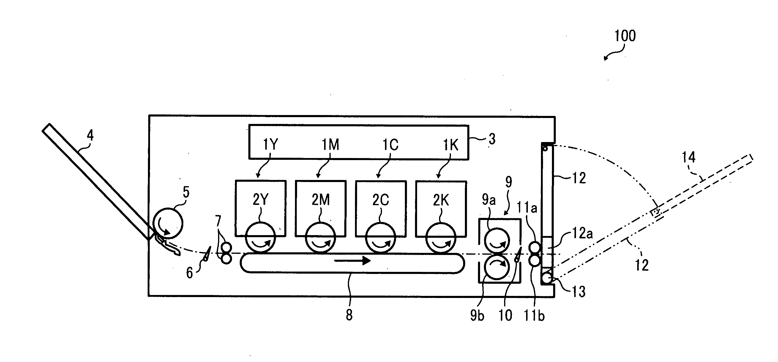
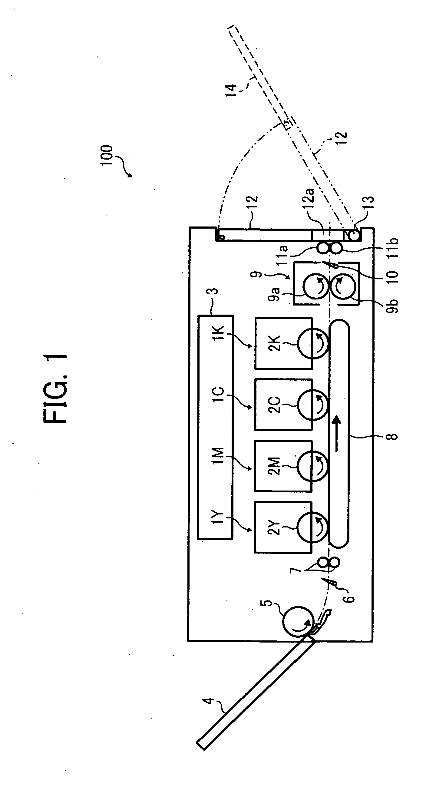
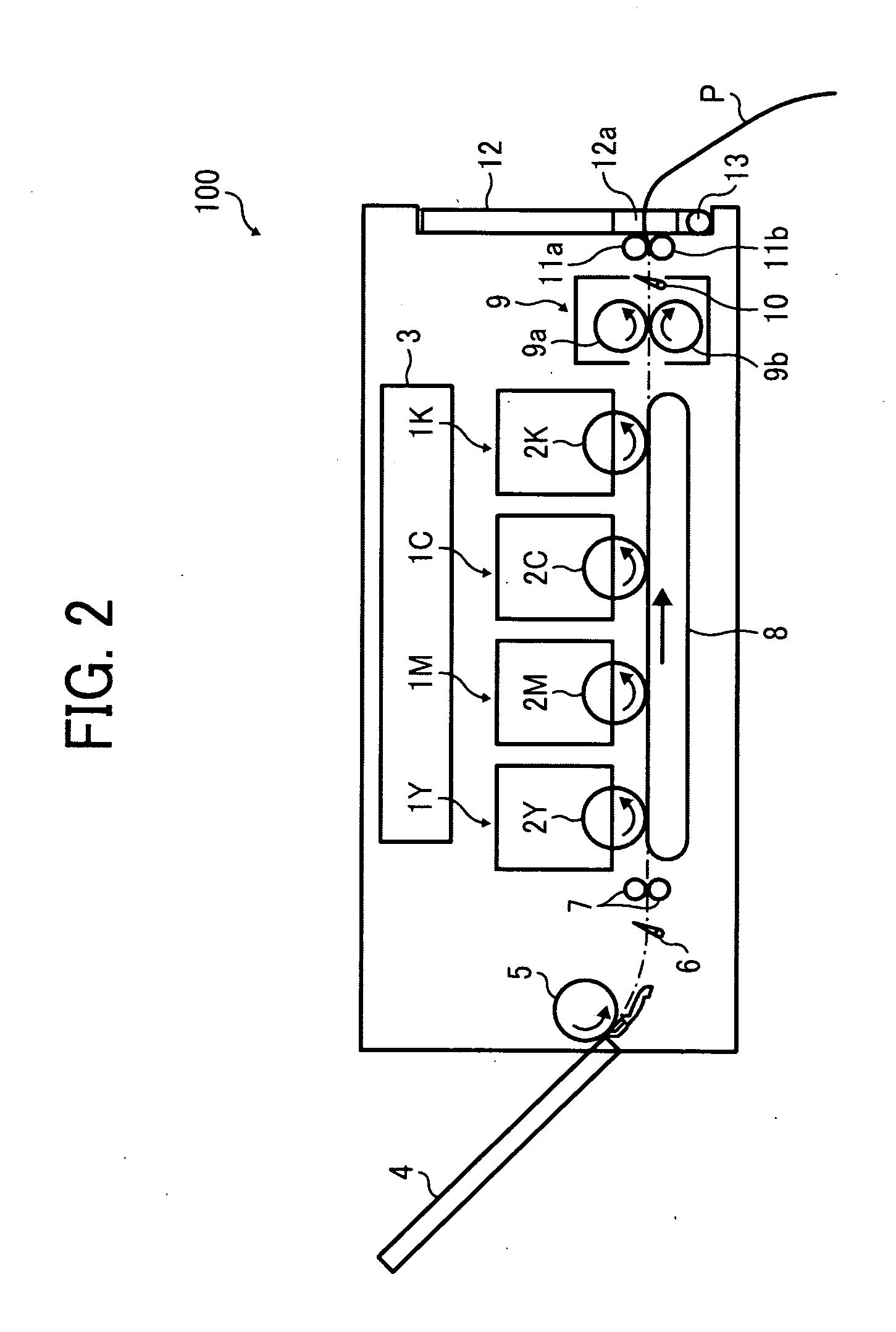
[0031]FIG. 1 is a vertical cross-sectional view illustrating a configuration of a full-color image forming apparatus 100 including a sheet discharger according to illustrative embodiments. The image forming apparatus 100 includes four image forming units 1Y, 1M, 1C, and 1K (hereinafter collectively referred to as image forming units 1), each forming an image of a specific col...


PUM


Abstract

A sheet discharger including a pair of rotary bodies to discharge a sheet to a discharge part by rotating while sandwiching the sheet and to hold the sheet, a part of which is discharged and exposed from a discharge exit of the sheet discharger, and a separation unit operatively connected to the pair of rotary bodies, including an operating part provided closer to the discharge exit than the pair of rotary bodies to support the sheet held by the pair of rotary bodies, that separates the pair of rotary bodies from each other by withdrawal of the sheet held by the pair of rotary bodies toward the discharge exit of the sheet discharger.

Description

PRIORITY STATEMENT[0001]The present patent application claims priority from Japanese Patent Application No. 2009-246466, filed on Oct. 27, 2009, in the Japan Patent Office, which is hereby incorporated herein by reference in its entirety.BACKGROUND[0002]1. Technical Field[0003]Illustrative embodiments described in this patent specification generally relate to a sheet discharger and an image forming apparatus including the sheet discharger.[0004]2. Description of the Related Art[0005]Related-art image forming apparatuses, such as copiers, printers, facsimile machines, and multifunction devices having two or more of copying, printing, and facsimile functions, typically form a toner image on a recording medium (e.g., a sheet of paper) according to image data using an electrophotographic method. In such a method, for example, a charger charges a surface of an image carrier (e.g., a photoconductor); an irradiating device emits a light beam onto the charged surface of the photoconductor t...

Claims


Application Information

Patent Timeline
Patent Type & Authority Applications(United States)
IPC IPC(8): G03G15/00B65H29/20
CPCB65H29/125G03G15/6552B65H31/20B65H2402/443B65H2404/1341B65H2404/143B65H2404/144B65H2404/1521B65H2405/11151B65H2405/11164B65H2405/1117B65H2405/324B65H2601/325B65H2801/06B65H2801/12B65H31/02
Inventor KIMURA, IPPEIMATSUYAMA, YASUOFUJII, IKUO
Owner RICOH KK
Why Eureka
Try Eureka