Milling Cutter

a cutter and milling technology, applied in the field of milling cutters, can solve the problems of exposing screws, time-consuming screw use, and longer production time, and less firm devices

Active Publication Date: 2011-04-28
ISCAR LTD
View PDF6 Cites 4 Cited by
  • Summary
  • Abstract
  • Description
  • Claims
  • Application Information

AI Technical Summary

Benefits of technology

[0019]wherein the raised portion is located in the aperture of the cutter body.

Problems solved by technology

The use of screws is time consuming and may be disadvantageous in that rotative motion is imparted by the hub to the cutter body via the screws, thereby exposing the screws to shear forces which could damage them.
The pins and the engagement members are detached from the adapter members, which can result in longer production time and less firm device.

Method used


Image

  • Milling Cutter
  • Milling Cutter
  • Milling Cutter

Examples


first embodiment

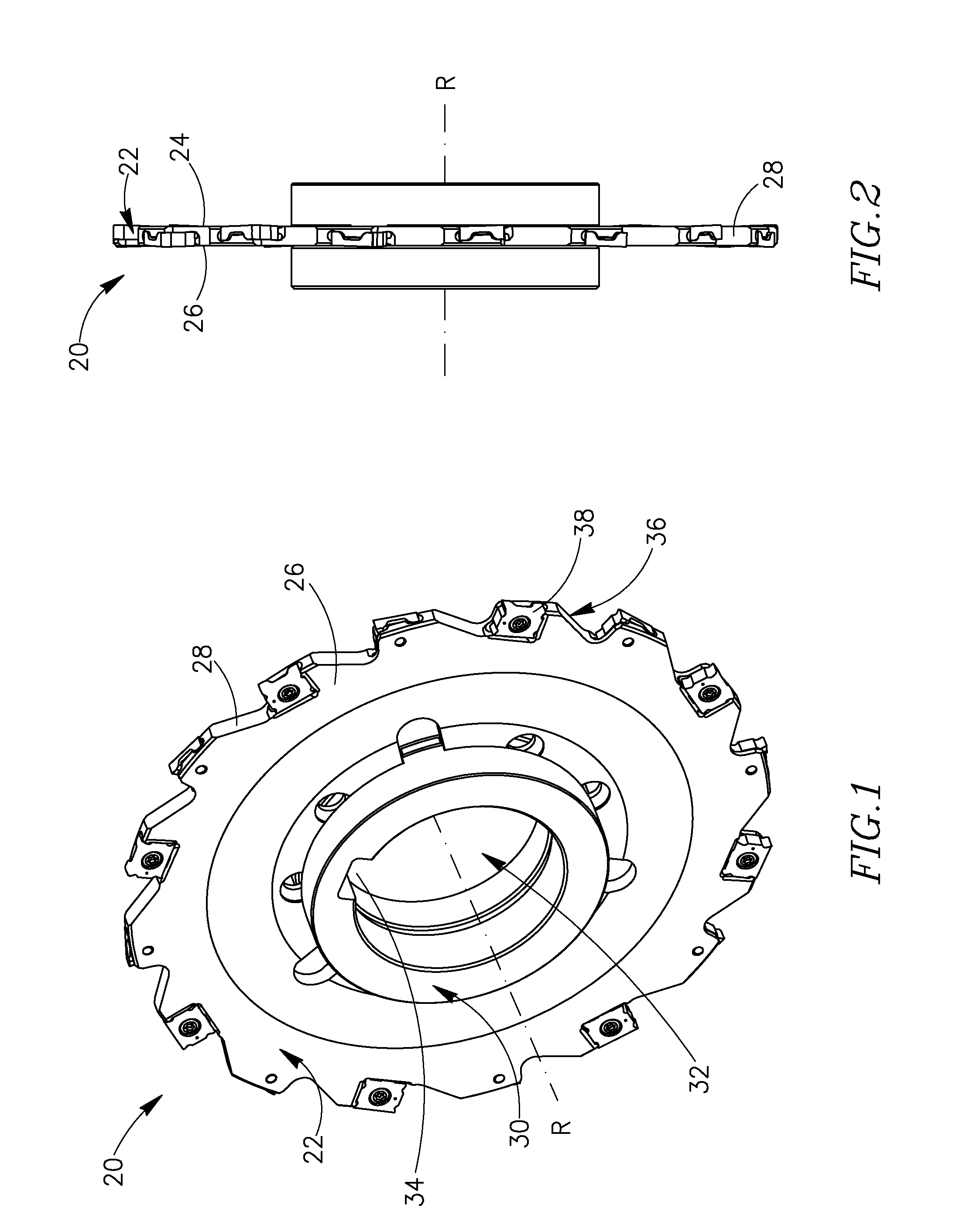
[0037]Attention is drawn to FIGS. 1 and 2, showing a milling cutter 20 in accordance with the present invention. The milling cutter 20 has a generally disk-shaped cutter body 22, having first and second opposing, generally parallel, side surfaces 24, 26 and an outer peripheral surface 28 extending between the two side surfaces 24, 26. The milling cutter 20 has an axis of rotation R which is perpendicular to the two side surfaces 24, 26. The milling cutter 20 has a hub 30 with an axially centered hub hole 32 for receipt of a support shaft of a machine spindle (not shown). Rotative motion is imparted to the hub 30 of the cutter via a drive key (also not shown) which mates with a drive keyway 34. A plurality of circumferentially spaced apart cutting portions 36 are located around the outer peripheral surface 28 of the cutter body 22, each cutting portion 36 being provided with a cutting insert 38.

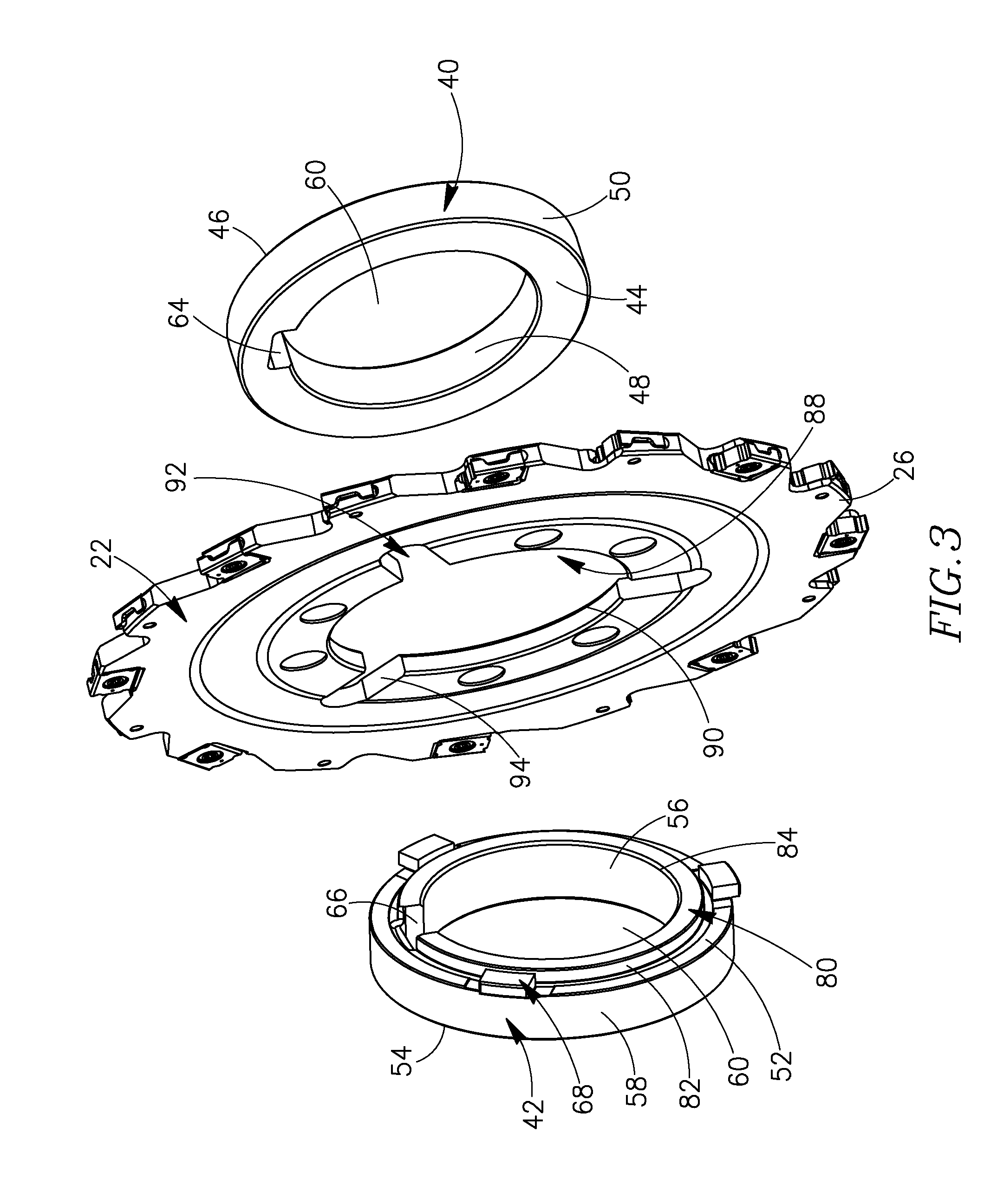
[0038]Attention is now additionally drawn to FIG. 3. The hub 30 includes first and second ...

second embodiment

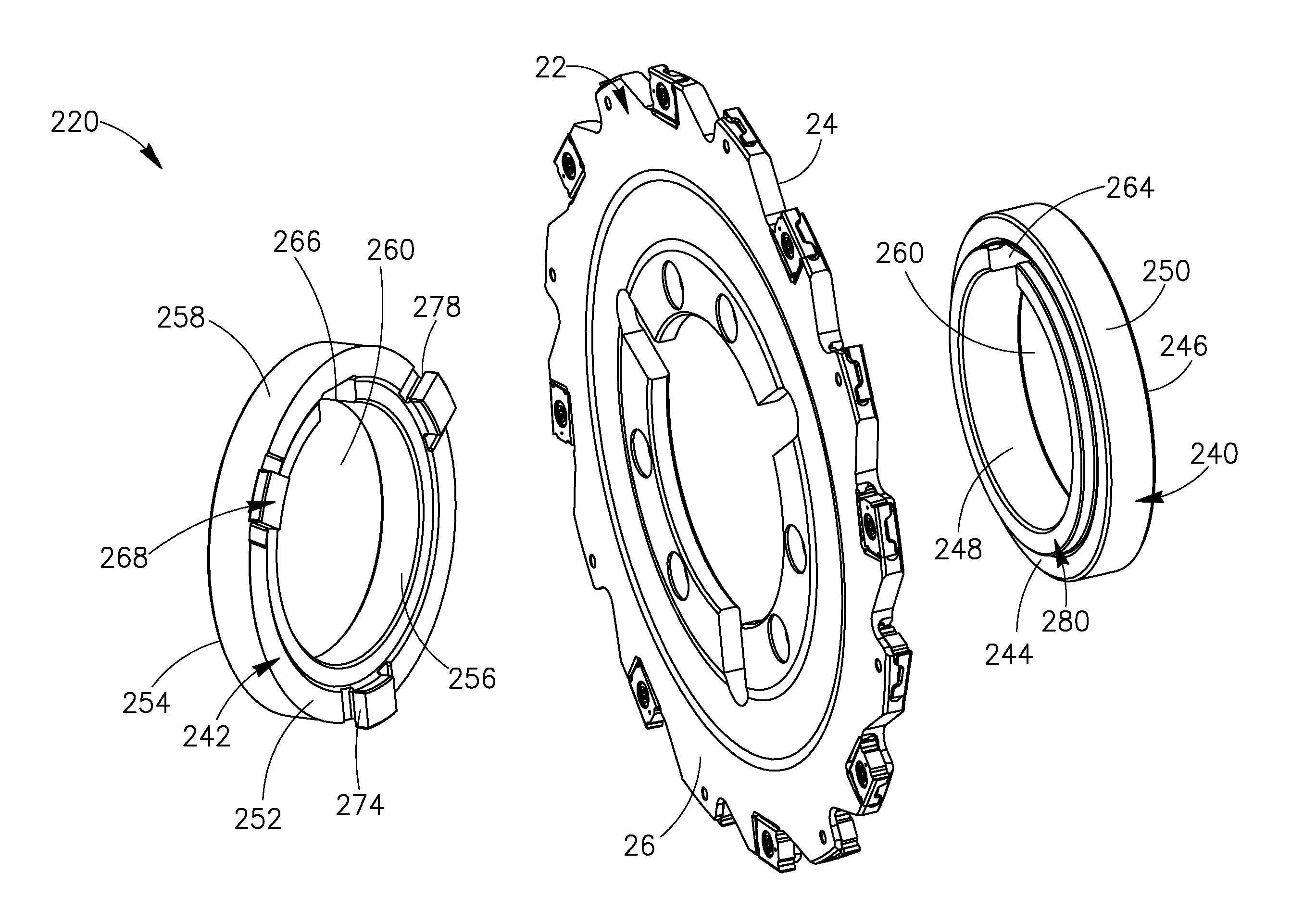
[0052]In accordance with the present invention, the milling cutter 220 is assembled by placing the second adapter member 242 adjacent the second side surface 26 of the cutter body 22 with the protrusions 268 adjacent the slots 92. The second adapter member 242 is urged towards the cutter body 22 until the second inner side wall 252 abuts the second side surface 26. In this position each protrusion 268 is fully inside the slot 92 with the peripheral surfaces 274 in juxtaposition with the slot inner surface 94.

[0053]All that remains is to urge the first adapter member 240 towards the partially assembled milling cutter 220. This is done by placing the first adapter member 240 adjacent the first side surface 24 with the raised portion 280 located adjacent the aperture 88. In this position the raised portion 280 is fully inside the aperture 88 with the outer surface 282 in juxtaposition with the aperture inner surface 90, the first inner side wall 244 abuts the first side surface 24, and...


PUM

PropertyMeasurementUnit
axis of rotationaaaaaaaaaa
of rotationaaaaaaaaaa
shapeaaaaaaaaaa

Abstract

A milling cutter includes a disk like cutter body having radially directed slots and a central aperture. An exchangeable hub of the milling cutter has two adapter members located on either side of the cutter body and has an inner side wall. One of the adapter members has at least two protrusions formed on the adapter inner side wall and one of the two adapter members has a raised portion located on the adapter inner side wall. The adapter members are secured to the cutter body by the protrusions positioned in the slots and the raised portion positioned in the central aperture.

Description

FIELD OF THE INVENTION[0001]The present invention relates to milling cutters and in particular to milling cutters with disk like cutter bodies.BACKGROUND OF THE INVENTION[0002]Such milling cutters are typically used for slotting operations and have a hub with an axially centered hole for receipt of a support shaft of a machine spindle. Since the hole has a given diameter, the milling cutter can only be used with a shaft of a given diameter.[0003]Milling cutters with exchangeable hubs are also known, wherein hubs can be prepared with any required hole diameter. When it is required to use the milling cutter with a support shaft having a diameter different from that of the hole diameter, the hub which is attached to the cutter body can be removed and a new hub with the required diameter can be attached to the cutter body in its place. However they generally employ screws (or bolts) to attach the hub to the cutter body. The use of screws is time consuming and may be disadvantageous in t...

Claims


Application Information

Patent Timeline
Patent Type & Authority Applications(United States)
IPC IPC(8): B23C5/08B23C5/26B23P11/00
CPCB23C5/08B23C5/26Y10T407/2202Y10T82/10Y10T407/23Y10T407/19Y10T407/1906Y10T407/1934Y10T29/49826Y10T407/20
Inventor KADOSH, SHIMONBARHOOM, YOUSEF
Owner ISCAR LTD
Why Eureka
Try Eureka