Balloon Encapsulated Catheter Tip

a catheter tip and balloon technology, applied in balloon catheters, catheters, stents, etc., can solve the problems of top over and blockage of drainage apertures, damage to any tissue structure, tip of catheter exposed, etc., to achieve easy rolling, enhance lubricity, and prevent sticking together

Active Publication Date: 2011-04-28
POIESIS MEDICAL
View PDF38 Cites 63 Cited by
  • Summary
  • Abstract
  • Description
  • Claims
  • Application Information

AI Technical Summary

Benefits of technology

[0010]The needs, disadvantages and limitations of the background art discussed above are overcome by the present invention. The instant invention is generally related to catheters, and more specifically, the instant invention provides a catheter assembly or catheter tip that includes a first balloon constructed and arranged to encapsulate the tip of the catheter to prevent the drawbacks of the prior art, and a second balloon to position the catheter within a body duct, cavity, or vessel. The catheter tip includes a cap having a stem portion and a sleeve portion secured to or integrally formed with the cap. The tip and sleeve are preferably constructed of resiliently flexible biocompatible material(s). The cap portion of the tip is constructed and arranged to be attached to the distal end of a catheter tube while the optional stem is inserted into the drain lumen of the catheter tube. The attached sleeve portion is extended over the outer surface of the end portion of the catheter tube and is selectively attached to the outer surface of the catheter tube in a manner that forms a first balloon positioned to encircle the cap at the distal end of the tube, and at least one second balloon positioned along the catheter tube to retain and / or position the catheter within a body cavity, duct or vessel. The balloons are expandable by admitting a preferably sterile fluid through one or more control lumen(s) extending through the catheter tube. The control lumens extend along the catheter tube substantially parallel to the drain lumen. Each control lumen is preferably provided with at least one aperture extending through the side wall of the catheter tube positioned in the area of one or more of the balloons to allow the fluid to enter the balloon from the lumen. The tip and sleeve are both preferably made of a biocompatible elastomeric material such as, but not limited to, natural rubber latex, synthetic rubber, plastic and silicone and may be prepared, as is known in the art, to include additives, suspensions and / or coatings specially utilized in the process of fabricating catheter balloons or used to prevent sticking together in storage or enhance lubricity. In addition, the inner and / or outer surfaces of the sleeve may include thick and / or thin sections, ribs or portions to cause the balloon to inflate to a desired shape. The tip and sleeve may be fabricated by any suitable process which may include but should not be limited to injection molding, dipping, vacuum forming, roto-molding, blow molding or suitable combination(s) thereof. In a most preferred embodiment, the sleeve is formed in an inside-out arrangement. After forming, the sleeve portion is preferably rolled, much like that of a condom. The tip is assembled to the catheter tube by inserting the stem portion of the plug into the central lumen of the catheter tube until the lower surface of the cap contacts the distal end of the catheter tube. Adhesive, solvents, fillers, radio frequency (RF) welding, laser welding or suitable combinations thereof may be utilized to secure the tip to the tube and / or seal the distal end of the catheter tube. The sleeve material may then be rolled over the outer surface of the catheter tube. At least two spaced apart and circumferentially extending bands of adhesive are positioned about the end portion of the catheter tube to secure the sleeve to the outer surface of the tube while forming the two balloons. Varying the width of the adhesive bands or distance between the adhesive bands allows the size of the balloons to be varied. It should be noted that solvents, radio frequency (RF) welding, laser welding or suitable combinations thereof may be utilized to secure the sleeve to the outer surface of the tube forming the two balloons. It should also be noted that the sleeve portion may be dipped into a solution that serves to expand the sleeve material before or after attachment to the catheter tube, such as an alcohol-based fluid, benzene, ether or the like. This expansion may allow for the sleeve to be easily rolled over the outer surface of the catheter tube, or alternatively, slid over the catheter tube, if left un-rolled. It should further be noted that the portion of the sleeve between the bands of adhesive may be removed, or the second balloon may be formed from a second sleeve of material without departing from the scope of the invention.

Problems solved by technology

This connection allows the tip to move relative to the balloon and can easily cause top over and blockage of the drainage aperture.
One of the major disadvantages of the '316 patent is that the tip of the catheter is exposed and can damage any tissue structure that the catheter may be inserted within.
A shortcoming of the '371 patent, however, includes the fact that the drainage aperture is placed at the distal end of the catheter, resulting in a greater tendency to have the mucosal lining of the bladder being drawn into the drainage port when in use.
A drawback to the '992 catheter is that the tip is not completely covered increasing the risk of contact with tissue structures, resulting in damage and leading to increased risk of infection.

Method used


Image

  • Balloon Encapsulated Catheter Tip
  • Balloon Encapsulated Catheter Tip
  • Balloon Encapsulated Catheter Tip

Examples


Embodiment Construction

[0051]While this invention is being described in its preferred embodiment as having a definitive catheter, it should be understood that the catheter is a commercially available item and that the invention is applied thereto and, as will be appreciated by one skilled in this technology, that the invention has utility for other types of catheters, some of which are disclosed in U.S. Pat. No. 4,351,342, supra.

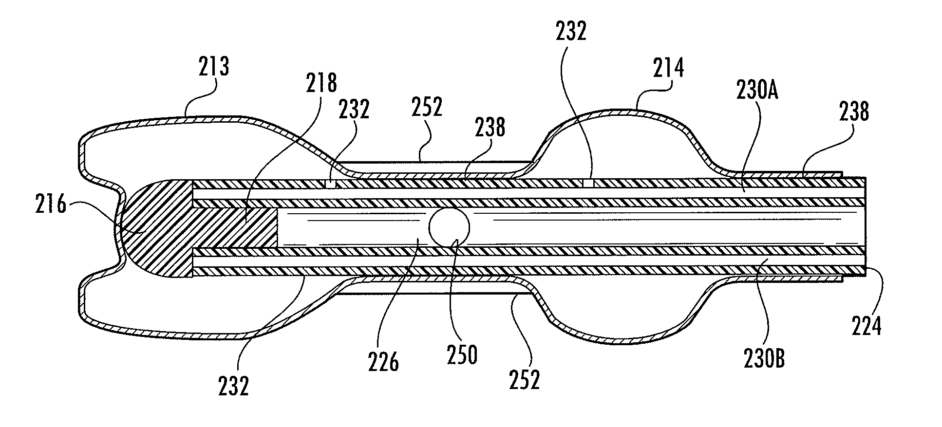
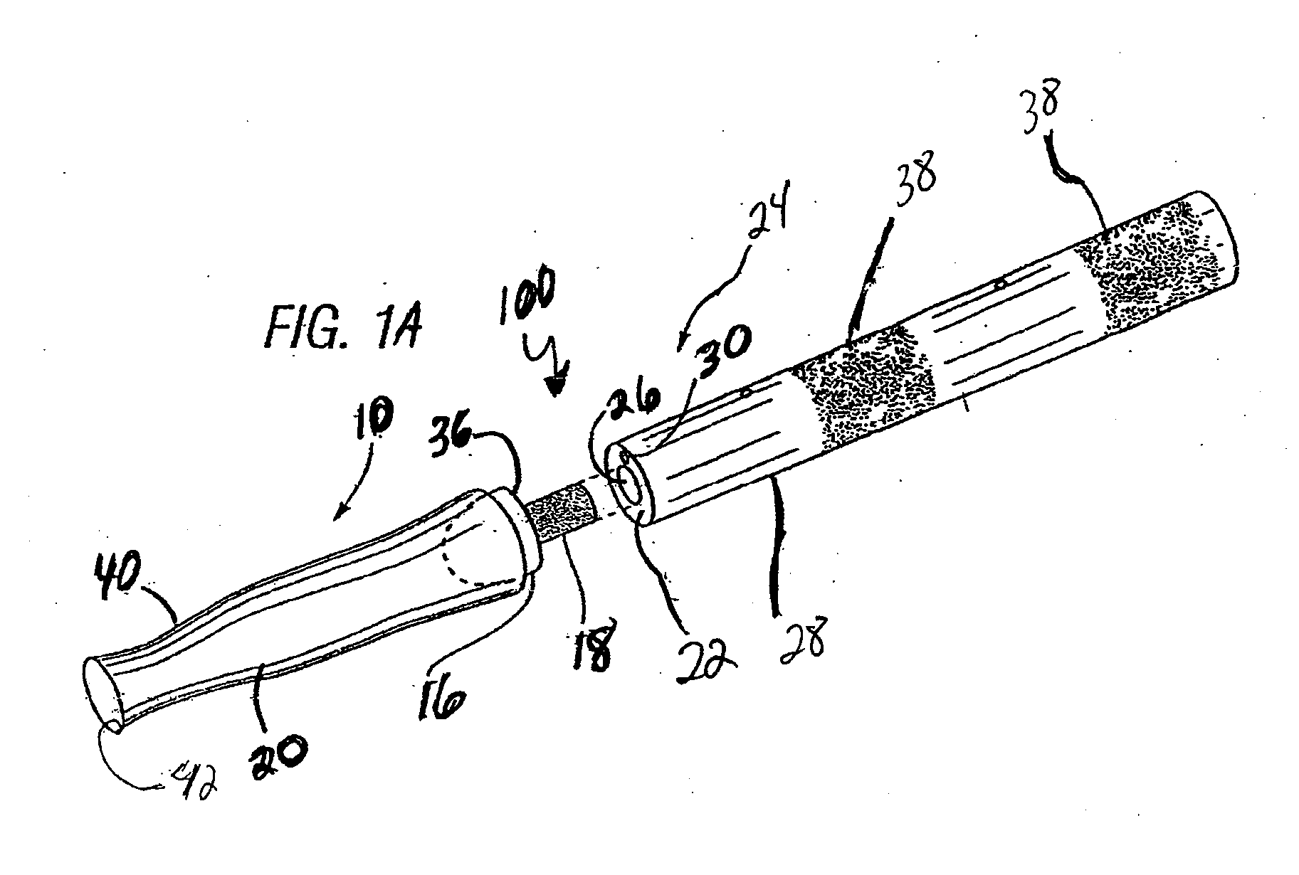
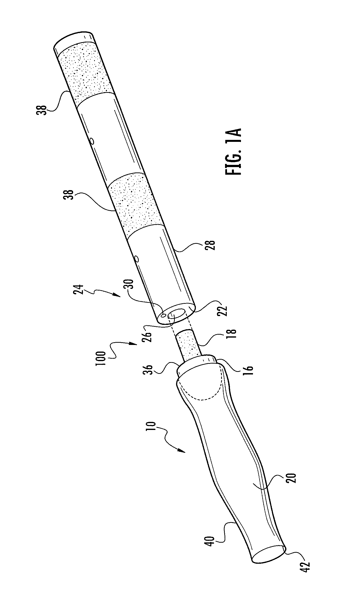
[0052]Referring to FIGS. 1-6, the instant invention provides a catheter assembly 100 or catheter tip 10 that includes a first balloon 13 constructed and arranged to encapsulate the distal end 12 of the catheter to prevent the drawbacks of the prior art, and a second balloon 14 to position the catheter within a body duct, cavity, or vessel (not shown). The catheter tip 10 includes a cap 16 preferably having a stem portion 18 and a sleeve portion 20 secured to or integrally formed with the cap. The tip 10 and sleeve 20 are preferably constructed of resiliently flexible biocompatible...


PUM


Abstract

This invention is generally related to catheters for insertion into a body cavity, duct or vessel, and more particularly to a tip or plug for a catheter. The catheter tip is constructed and arranged to form a seal on the end portion of the catheter tube, while a sleeve secured or formed integrally to the tip cooperates with the catheter tube to form a first balloon that encapsulates the tip of the catheter and a second balloon that positions the catheter within the body cavity, duct or vessel.

Description

CROSS REFERENCE TO RELATED APPLICATIONS[0001]This application claims benefit of the filing date of Provisional Application 61 / 254,950, filed on Oct. 26, 2009, the contents of which are herein incorporated by reference. This application is also related to U.S. Pat. No. 4,351,342 entitled, “BALLOON CATHETER”, filed on Sep. 28, 1982, and issued to Bruce E. Wiita and J. Michael Teets, the contents of which are herein incorporated by reference.FIELD OF THE INVENTION[0002]This invention relates to medical devices, and more specifically to a balloon encapsulated catheter tip or plug that is constructed and arranged for insertion into a body cavity, duct or vessel.BACKGROUND OF THE INVENTION[0003]This invention is generally related to catheters for insertion into a body cavity, duct or vessel, and more particularly to a tip or plug for a catheter. The catheter tip is constructed and arranged to form a seal on the end portion of the catheter tube, while a sleeve secured or formed integrally ...

Claims


Application Information

Patent Timeline
Patent Type & Authority Applications(United States)
IPC IPC(8): A61M27/00A61F2/958
CPCA61M25/0069A61M25/007A61M25/1002A61M25/1011A61M2025/1093A61M2025/1047A61M2025/1065A61M2025/1086A61M25/1036
Inventor WIITA, GREGORY D.WIITA, BRUCE E.
Owner POIESIS MEDICAL
Why Eureka
Try Eureka