Medical implant

a technology of medical implants and implants, applied in the field of medical implants, can solve the problem that the proportion of occlusion means cannot be prevented from exiting, and achieve the effect of preventing the proportion of such occlusion means from exiting

Active Publication Date: 2011-04-28
TYCO HEALTHCARE GRP LP
View PDF98 Cites 33 Cited by
  • Summary
  • Abstract
  • Description
  • Claims
  • Application Information

AI Technical Summary

Benefits of technology

Occlusion means of this kind are meant to stabilize the aneurysm wall so that further filamentous occlusion means can be inserted subsequently without running the risk of causing wall ruptures. Although such occlusion means may be viewed as an improvement compared to non-preformed occlusion means in that they provide increased safety of operation, imminent rupturing danger still exists however in areas of the aneurysm wall, in particular those adjacent to faces and vertices as well as edges of the polyhedrons, especially as a result of the occlusion helixes subsequently inserted into the aneurysm. Moreover, because of the largely openly configured tertiary structure of such occlusion means the subsequently inserted occlusion means or portions of such occlusion means can only be prevented from exiting through the neck of the aneurysm primarily in the case of small-neck aneurysms.
Arranging the proximal end of the helix forming the pentagonal dodecahedron on a vertex or corner point was found to be particularly beneficial. Since the neck of the aneurysm is usually located within a face of the polyhedron this makes it difficult for the last-inserted portion of the helix to slip out of the neck and helps to prevent the helix from being flushed out which anyway is improbable due to the plurality of the faces, the close contact with the wall of the aneurysm and the strain that as a rule prevails inside the aneurysm. The distal end of the helix is preferably arranged in a face and is the point where the first loop starts; advantageously here is a mainly atraumatic supporting location on a side facing away from the neck of the aneurysm.

Problems solved by technology

Moreover, because of the largely openly configured tertiary structure of such occlusion means the subsequently inserted occlusion means or portions of such occlusion means can only be prevented from exiting through the neck of the aneurysm primarily in the case of small-neck aneurysms.

Method used


Image

  • Medical implant
  • Medical implant
  • Medical implant

Examples


Embodiment Construction

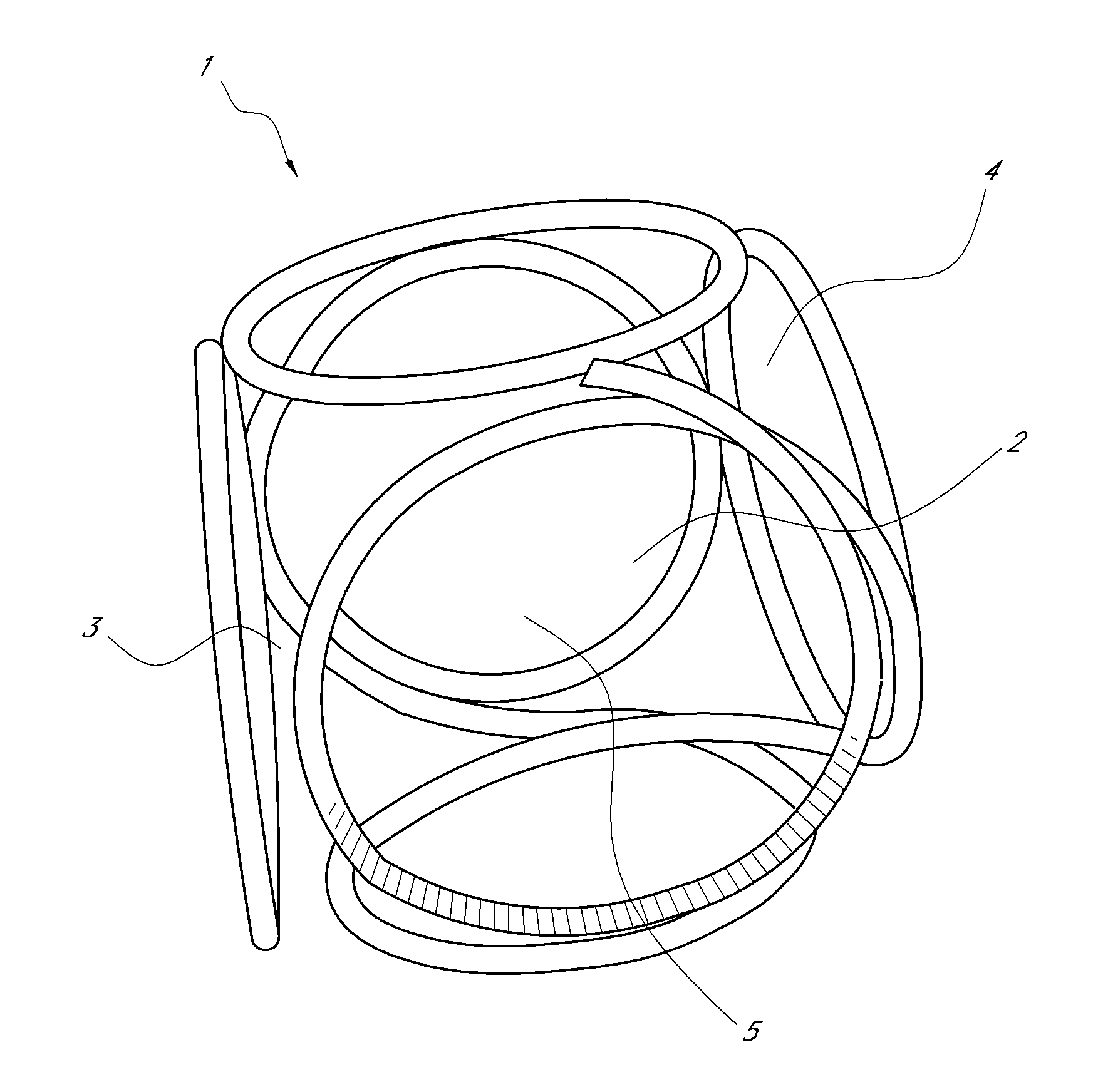
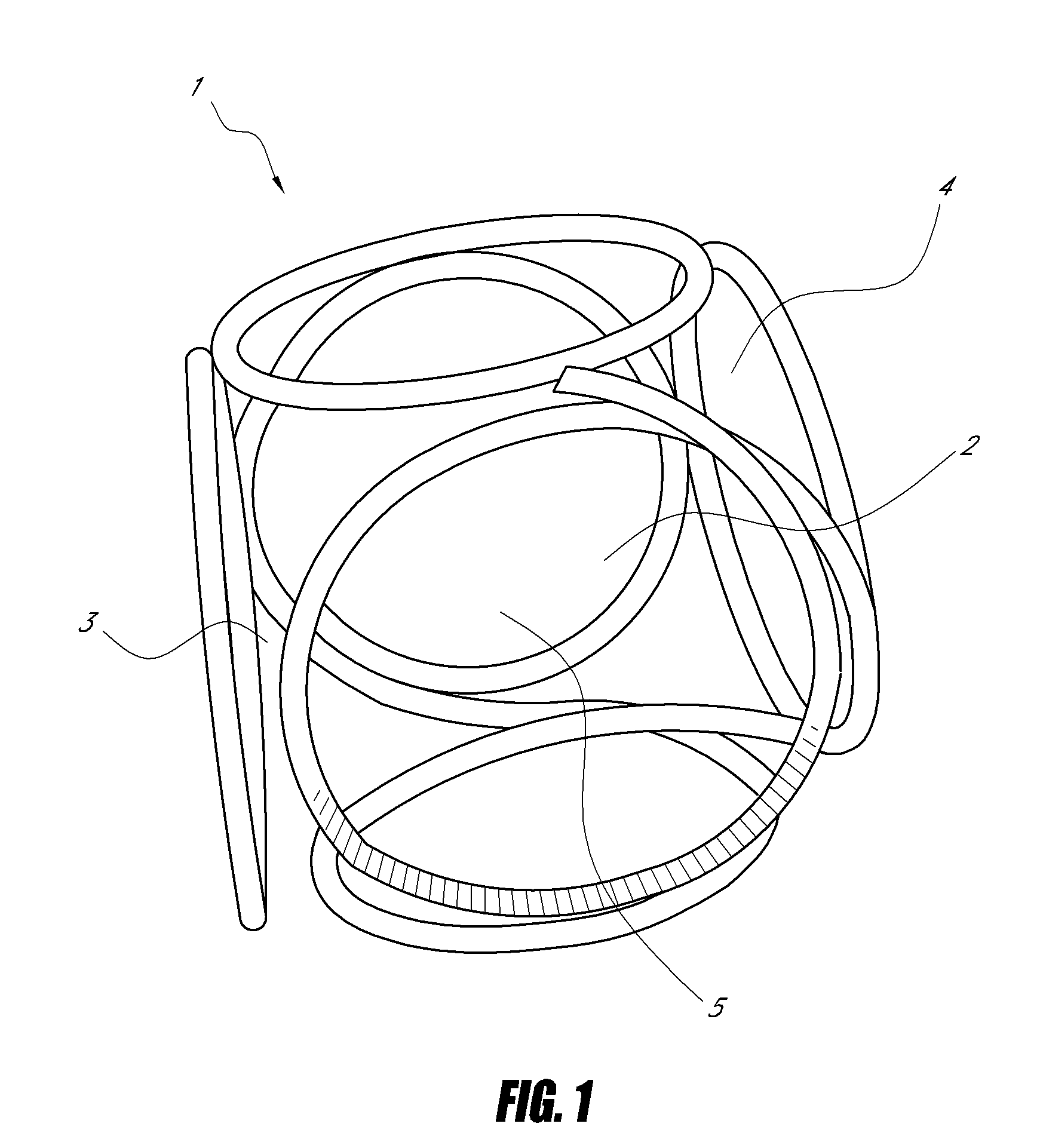
FIG. 1 represents a cube-shaped implant 1 of enlarged size reflecting the state of the art. The open configuration, especially of the faces 2 and vertex areas 4, but also of edges 3, is to be seen as a weak point of such implants 1 because the aneurysm wall in contact with them is particularly prone to rupture. In addition, the insufficient packing density of the implant 1 in the vicinity of said areas 2, 3 and 4 only prevents to a minor extent implants subsequently placed for the purpose of filling the inner hollow space 5 from being expelled again.

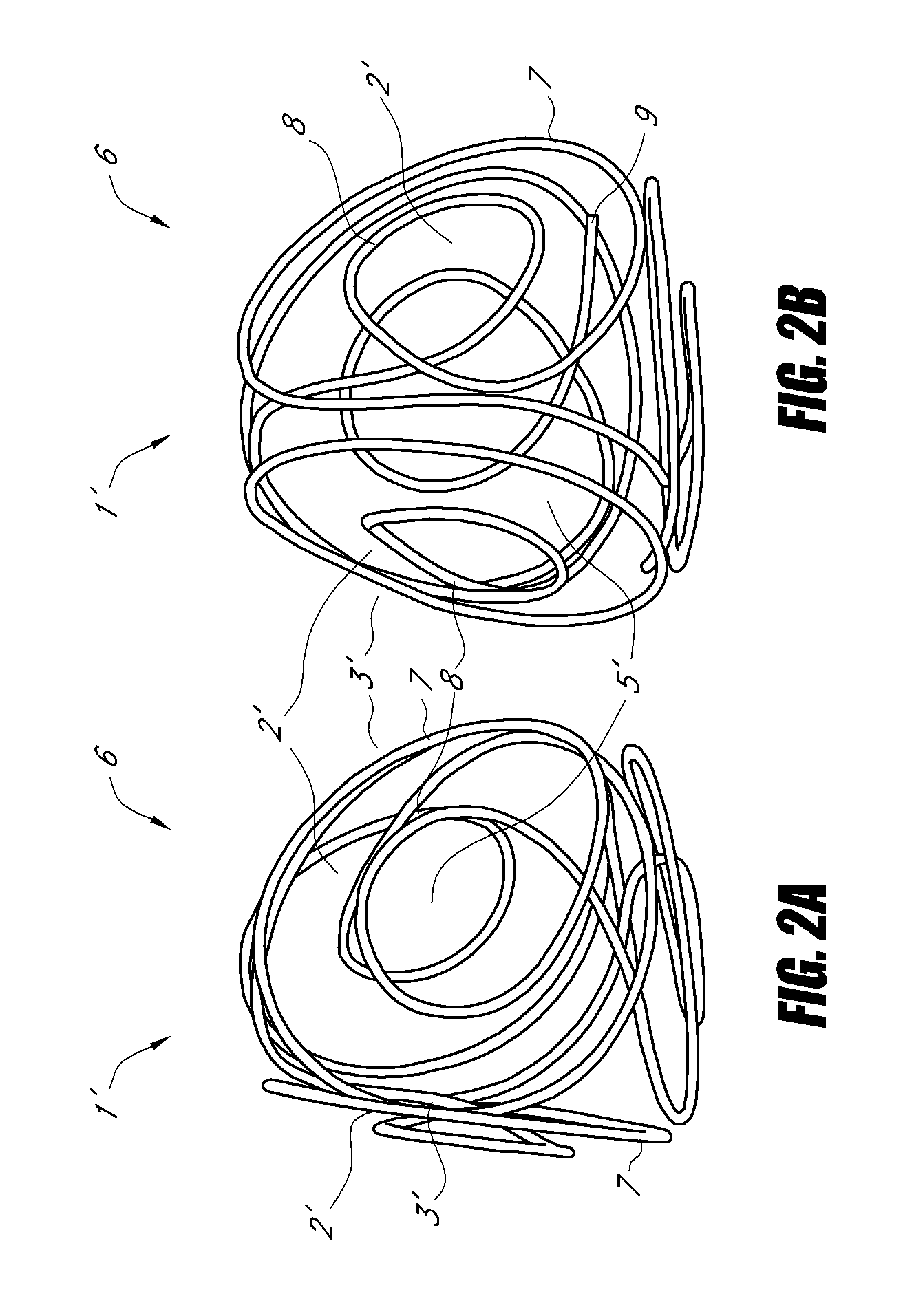
FIG. 2 shows two views 2a and 2b of a tetrahedron-shaped implant 1′ according to the invention, said implant having assumed its three-dimensional tetrahedral tertiary structure. The faces 2′ of tetrahedron 6 are built up by two uniformly sized large loops 7, two of which in each case being adjacently positioned, with the projections of the large loops 7 extending into the space constituted by the sectional areas of two neighboring large ...


PUM

PropertyMeasurementUnit
diameteraaaaaaaaaa
diameteraaaaaaaaaa
diameteraaaaaaaaaa

Abstract

The invention relates to a medical implant in the form of an elongated helix wherein at least one part of the helix is preformed in such a manner that it has a secondary structure of identically sized loops which it assumes during implantation at the placement site, with said structure in turn forming at the placement site during implantation a polyhedral tertiary structure, and the polyhedron being provided with at least one additional loop.

Description

BACKGROUND1. Field of the InventionThe invention relates to a medical implant in the form of an elongated helix wherein at least one part of the helix is preformed in such a manner that it has a secondary structure which it assumes during implantation at the placement site, with said structure in turn forming at the placement site during implantation a polyhedral tertiary structure, with each face of the polyhedron being built up by a loop.The invention, furthermore, relates to a device for the implantation of such implants in body cavities and vessels.2. Description of the Related ArtKnown in the art is the use endovascular techniques for the occlusion of body cavities or vessels such as arteries, veins, fallopian tubes or vascular deformities such as, for example, vascular aneurysms. In this case, the closure element (also termed occlusion means) is usually introduced by means of an insertion aid through a catheter into the cavity to be occluded and deposited therein by means of o...

Claims


Application Information

Patent Timeline
Patent Type & Authority Applications(United States)
IPC IPC(8): A61F2/02
CPCA61B17/12022A61B17/12113Y10T29/49826A61B2017/00526A61B2017/00867A61B17/12145
Inventor MONSTADT, HERMANNHENKES, HANSFLESSER, ACHIMHANNES, RALF
Owner TYCO HEALTHCARE GRP LP
Why Eureka
Try Eureka