
Control device for internal combustion engine

a control device and internal combustion engine technology, applied in the direction of electric control, machines/engines, instruments, etc., can solve the problem that the above-mentioned three operation cannot be controlled and adjusted

Active Publication Date: 2011-04-28
TOYOTA JIDOSHA KK
View PDF9 Cites 13 Cited by
  • Summary
  • Abstract
  • Description
  • Claims
  • Application Information

AI Technical Summary

Benefits of technology

[0007]The present invention has been made in view of the above circumstances. An object of the present invention is to provide a control device that is used with an internal combustion engine in which the air-fuel ratio in the vicinity of an ignition plug differs from the overall air-fuel ratio in a cylinder, and capable of properly fulfilling demands concerning various capabilities of the internal combustion engine by accurately reflecting the demands in the operation of each actuator.
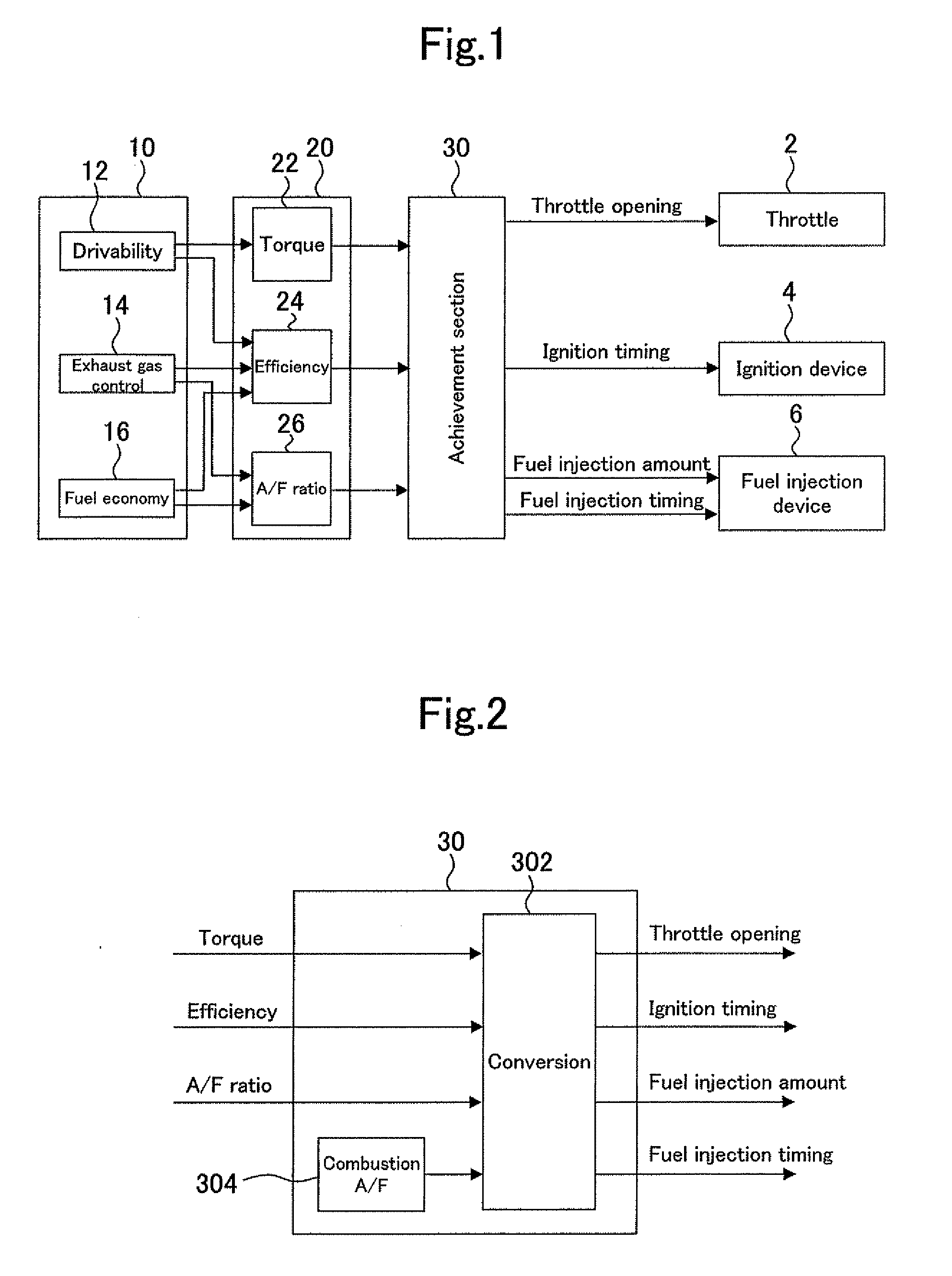
[0011]According to the present invention, a fourth operation amount, which adjusts the air-fuel ratio distribution in a cylinder, is set in addition to the three operation amounts, namely, the intake air amount adjustment valve opening, ignition timing, and fuel injection amount. When the air-fuel ratio in the entire cylinder is uniform, torque control can be exercised by adjusting the intake air amount, efficiency, and air-fuel ratio with the aforementioned three operation amounts. In the internal combustion engine to be controlled by the present invention, however, the air-fuel ratio in the vicinity of the ignition plug differs from the overall in-cylinder air-fuel ratio. Therefore, it is difficult to exercise precise torque control in accordance with the intake air amount, efficiency, and overall in-cylinder air-fuel ratio alone. In this respect, the present invention uses the aforementioned fourth operation amount to adjust the in-cylinder air-fuel ratio distribution. This makes it possible to control the air-fuel ratio in the vicinity of the ignition plug in addition to the overall in-cylinder air-fuel ratio. Consequently, precise torque control can be exercised.
[0016]According to another aspect (fourth aspect) of the present invention, the means for setting the aforementioned operation amounts has a fixed value representing the target value for the air-fuel ratio in the vicinity of the ignition plug in each operating state of the internal combustion engine. When each operation amount is calculated with the target value changed to match each operation state of the internal combustion engine, control can be exercised so that the air-fuel ratio in the vicinity of the ignition plug is optimized for each operating state of the internal combustion engine. This makes it possible to enhance the accuracy of torque control.
[0017]According to another aspect (fifth aspect) of the present invention, the means for setting the aforementioned operation amounts predefines a target relationship between the overall in-cylinder air-fuel ratio and the air-fuel ratio in the vicinity of the ignition plug. When this target relationship is used to determine the target value for the air-fuel ratio in the vicinity of the ignition plug from the target value for the air-fuel ratio, which is a controlled variable, and calculate each operation amount, control can be exercised so that the air-fuel ratio in the vicinity of the ignition plug is optimized for the overall in-cylinder air-fuel ratio. This makes it possible to enhance the accuracy of torque control.
[0019]According to still another aspect (seventh aspect) of the present invention, the means for setting the aforementioned operation amounts first calculates the intake air amount adjustment valve opening, ignition timing, and fuel injection amount in accordance with the target values for the three controlled variables, namely, the torque, efficiency, and air-fuel ratio. Next, the means for setting the aforementioned operation amounts calculates the fourth operation amount from the fuel injection amount, which is an operation amount, and the target value for the air-fuel ratio in the vicinity of the ignition plug. In other words, the three operation amounts, namely, the intake air amount adjustment valve opening, ignition timing, and fuel injection amount, are calculated directly from the target values for the three controlled variables, namely, the torque, efficiency, and air-fuel ratio, whereas the fourth operation amount is calculated from the fuel injection amount and the target value for the air-fuel ratio of a combustion gas in the vicinity of the ignition plug. When each operation amount is set by performing the above-described procedure, each of the target values for the controlled variables can be accurately reflected in the four different operation amounts including the fourth operation amount while avoiding the complication of a calculation process necessary for the conversion of the controlled variables to the operation amounts.

Problems solved by technology

However, such an adjustment cannot be made by controlling the above-mentioned three operation amounts alone.
However, the technology disclosed in JP-A-2003-301766 meets only some of such demands and still needs further improvement to accommodate a variety of demands about the internal combustion engine.

Method used


Image

  • Control device for internal combustion engine
  • Control device for internal combustion engine
  • Control device for internal combustion engine

Examples


first embodiment

[0051]A first embodiment of the present invention will now be described with reference to FIGS. 1 and 2.

[0052]First of all, the specifications for an internal combustion engine according to the first embodiment will be described as its prerequisites. The internal combustion engine according to the present embodiment operates while stratified charge combustion occurs. As actuators that control its operation, the internal combustion engine according to the present embodiment includes a throttle 2, which serves as an intake air amount adjustment valve; an ignition device 4, which adjusts the ignition timing; and a fuel injection device 6, which injects fuel directly into a cylinder. The specifications for the internal combustion engine according to the present embodiment are common to the internal combustion engine according to a second embodiment or a third embodiment, both of which will be described later.

[0053]A control device according to the present embodiment is configured as sho...

second embodiment

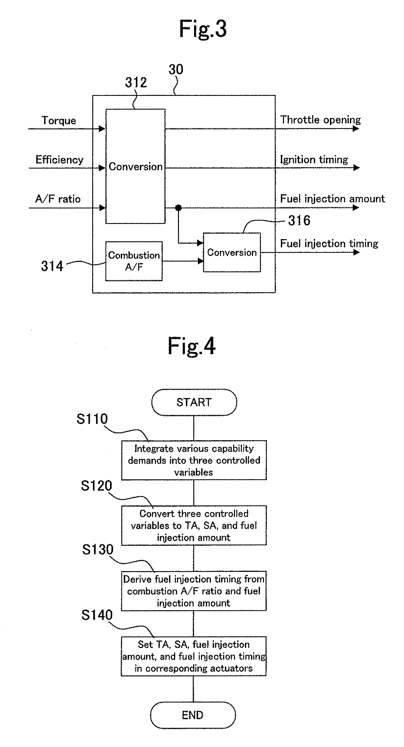
[0072]A second embodiment of the present invention will now be described with reference to FIGS. 1, 3, and 4.

[0073]The overall configuration of the control device according to the present embodiment is indicated by the block diagram in FIG. 1, as is the case with the first embodiment. The control device according to the present embodiment differs from the control device according to the first embodiment in the configuration and functions of the achievement section 30, which is an element of the control device. FIG. 3 is a block diagram illustrating the configuration of the achievement section 30 according to the present embodiment.

[0074]The achievement section 30 according to the present embodiment includes a conversion section 312, a conversion section 316, and a target combustion A / F setup section 314. In the first embodiment, the conversion section 302 corresponds to an inverse model of the internal combustion engine. In the present embodiment, however, the conversion section 312...

third embodiment

[0082]A third embodiment of the present invention will now be described with reference to FIGS. 1, 5, and 7.

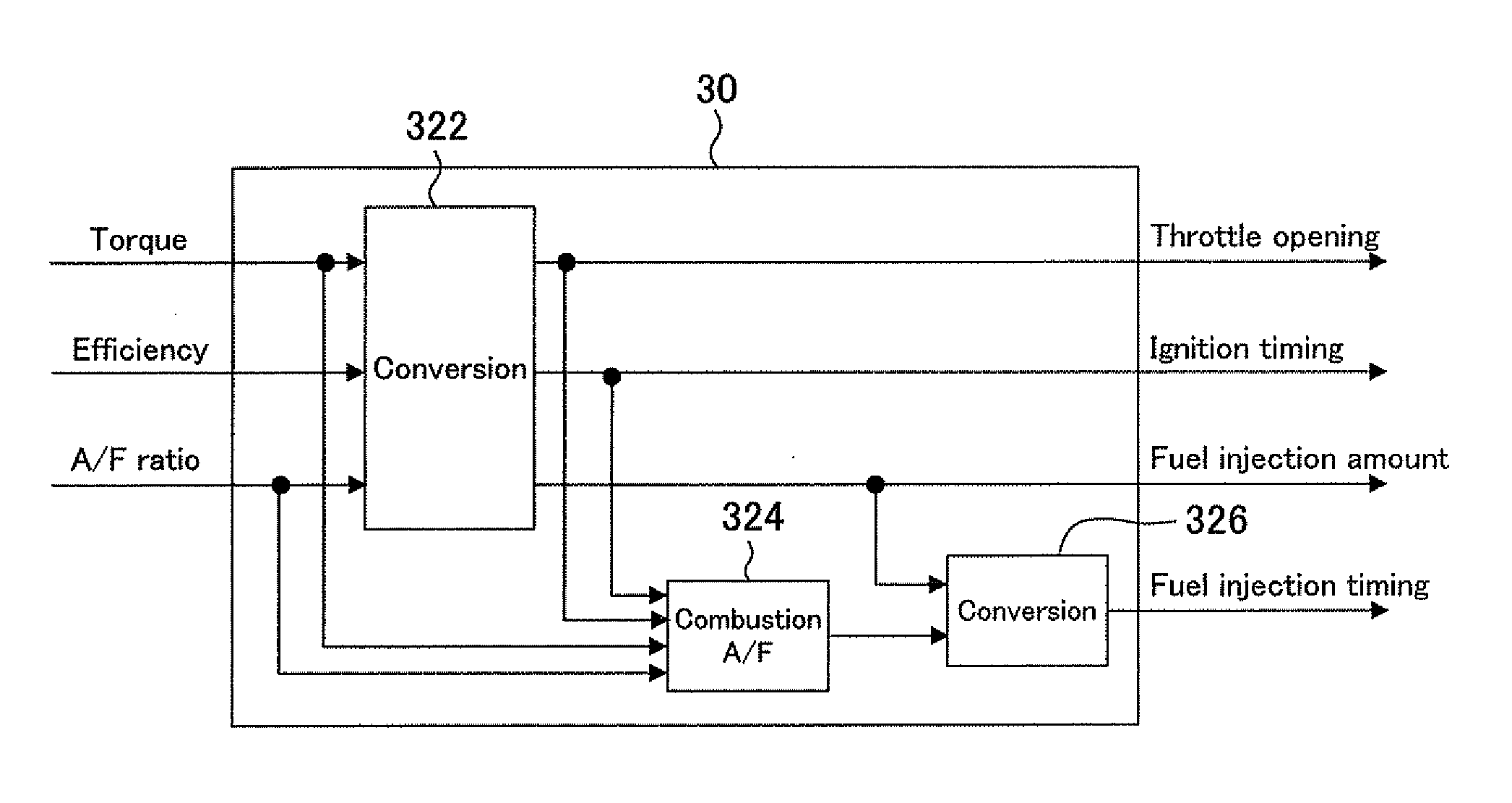
[0083]The overall configuration of the control device according to the present embodiment is indicated by the block diagram in FIG. 1, as is the case with the first embodiment. The control device according to the present embodiment differs from the control device according to the first embodiment in the configuration and functions of the achievement section 30, which is an element of the control device. FIG. 5 is a block diagram illustrating the configuration of the achievement section 30 according to the present embodiment.

[0084]The achievement section 30 according to the present embodiment includes a conversion section 322, a conversion section 326, and a target combustion A / F setup section 324. In the first embodiment, the conversion section 302 corresponds to an inverse model of the internal combustion engine. In the present embodiment, however, the conversion section 322,...


PUM


Abstract

Disclosed are a control device and a control method that are used with an internal combustion engine in which the air-fuel ratio in the vicinity of an ignition plug differs from the overall air-fuel ratio in a cylinder, and capable of properly fulfilling demands concerning various capabilities of the internal combustion engine by accurately reflecting each of the demands in the operation of each actuator. Three physical quantities, namely, a torque, an efficiency, and an air-fuel ratio, are used as controlled variables for the internal combustion engine. Target values for the controlled variables are then set by integrating at least some of demands concerning a capability of the internal combustion engine into the three physical quantities. Further, in accordance with the target values for the three controlled variables, namely, the torque, the efficiency, and the air-fuel ratio, three operation amounts, namely, an intake air amount adjustment valve opening, an ignition timing, and a fuel injection amount are set, and a fourth operation amount for adjusting the air-fuel ratio distribution in the cylinder is set.

Description

TECHNICAL FIELD[0001]The present invention relates to a control device for an internal combustion engine, and more particularly to a control device for an internal combustion engine in which the air-fuel ratio in the vicinity of an ignition plug differs from the overall air-fuel ratio in a cylinder.BACKGROUND ART[0002]A technology known as being related to internal combustion engine torque control is disclosed, for instance, in JP-A-2003-301766. This technology calculates an indicated torque demanded by a driver in accordance with an accelerator opening and determines a target air-fuel ratio in a control device. Next, this technology corrects the demanded indicated torque in accordance with torque efficiency relative to ignition timing and torque efficiency relative to the target air-fuel ratio, and determines a target throttle opening in accordance with a target air amount that is derived from the corrected torque. Further, this technology calculates an intake retard correction amo...

Claims


Application Information

Patent Timeline
IPC IPC(8): F02D43/00
CPCF02D37/02F02D41/0002F02D41/3029Y02T10/42F02D2041/1434F02D2250/18Y02T10/44F02D41/40Y02T10/40F02D41/04F02D41/14F02D41/30F02D43/00F02D41/3023
Inventor UEDA, KOICHISATA, KOTASOEJIMA, SHINICHIOHTSUKA, KAORU
Owner TOYOTA JIDOSHA KK
Learn More