
Temporary Removable Sole with Removable Cleats

a technology of cleats and soles, which is applied in the field of temporary enhancements to shoes, can solve the problems of not providing a stable, comfortable fit onto the shoe, difficult to attach to the shoe, and products that are not easily removable from the shoe, etc., and achieves the effects of quick and easy removal, improved traction, and quick and easy attachment and unattaching

Inactive Publication Date: 2011-05-05
KOE KROMPECHER PEDRO EDUARDO
View PDF25 Cites 23 Cited by
  • Summary
  • Abstract
  • Description
  • Claims
  • Application Information

AI Technical Summary

Benefits of technology

[0011]The present invention aims to solve the problems found in the prior art by introducing a temporary sole that can be attached and unattached quickly and easily to a wide variety of shoes. The temporary sole has holes in the front and in the back that allows a user to attach it easily to a shoe. The temporary sole may also include a strap that can be used to further secure the temporary sole to the shoe. The temporary sole also may include removable and replaceable cleats that can be fitted into the sole. In this manner, the present invention allows the wearers of the shoes to quickly take off or put on a temporary sole that may include cleats. This invention is ideal for attaching golf cleats or other athletic cleats to shoes or for providing better traction to the existing sole of a shoe.

Problems solved by technology

The most notable disadvantages to all of the below discussed products are: (1) the cleat or spike requires adhesive, screws, bolts, or other binding product to attach the cleat or spike to the sole of the product; (2) the cleats or spikes are not easily replaceable without the use of a tool or wrench; (3) the product appears bulky and does not provided a stable, comfortable fit onto the shoe; (4) the products are difficult to attach to a shoe, requiring latches, braces, clips or screws; (5) the products are not easily removable from the shoe; (6) the products are not easily mass produced, due primarily to their multiple moving parts; and (7) mass production of these products would not be cost effective.

Method used


Image

  • Temporary Removable Sole with Removable Cleats
  • Temporary Removable Sole with Removable Cleats
  • Temporary Removable Sole with Removable Cleats

Examples


Embodiment Construction

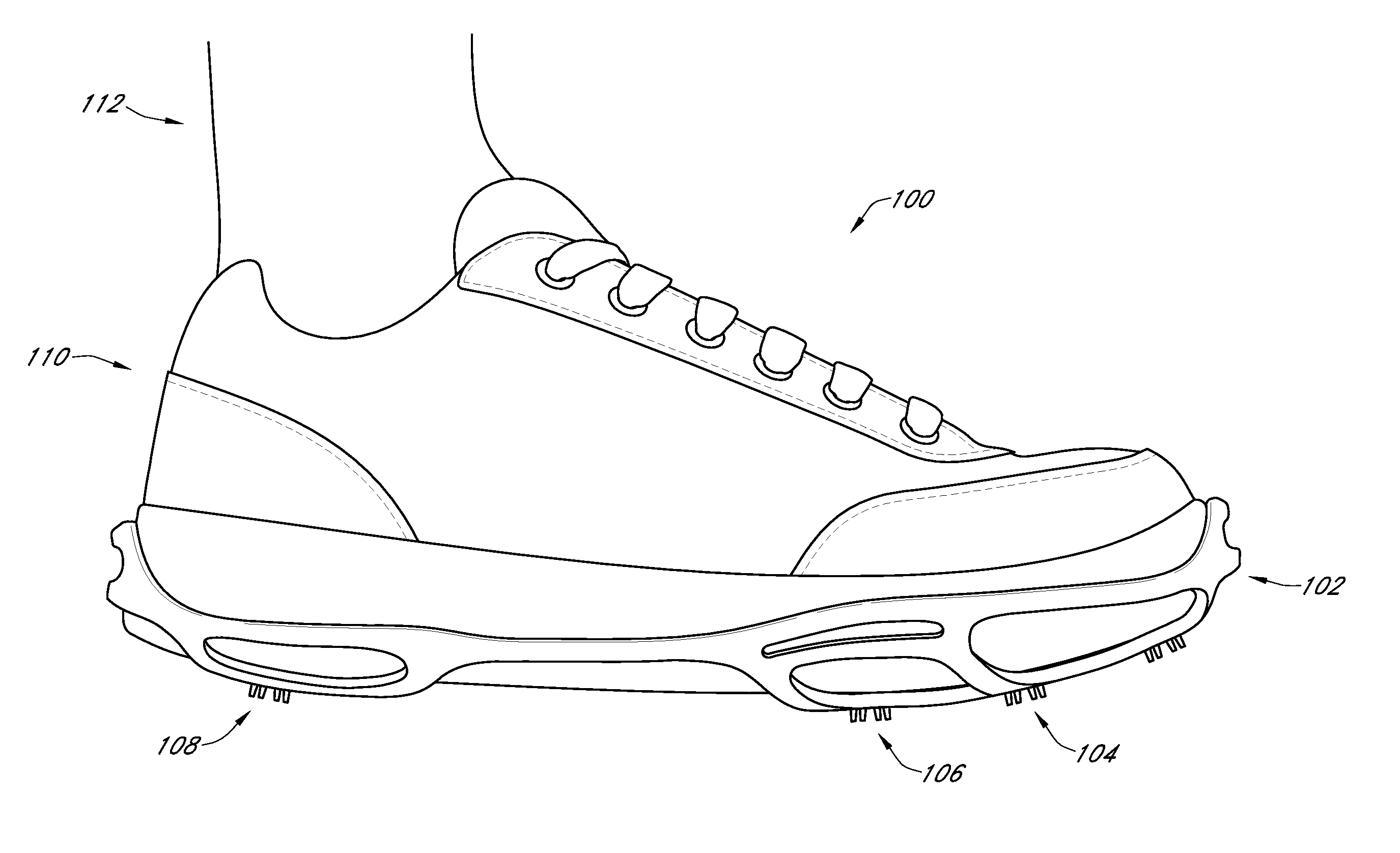
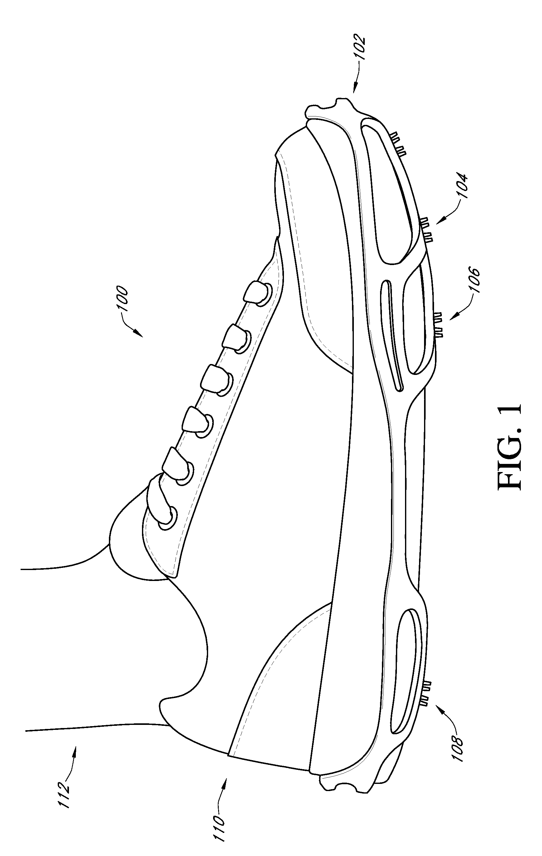
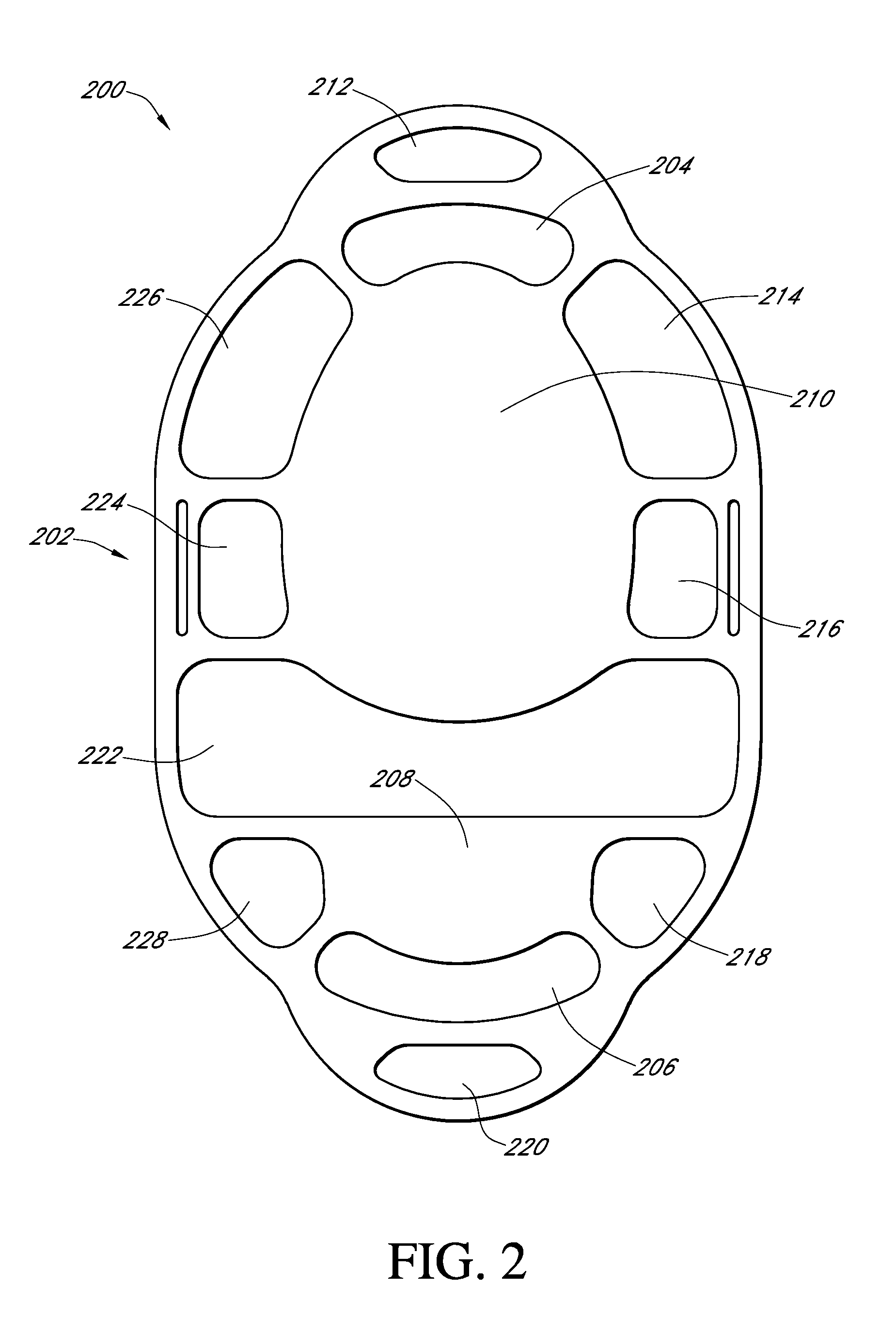
[0030]In accordance with an exemplary embodiment of the present invention, FIG. 1 illustrates a view of the present invention 100 affixed to a shoe 110. The shoe 110 may be a men's or women's shoe. Furthermore, the shoe 110 may be an athletic shoe, dress shoe, boot, or specialty shoe of any size, including children's size. In the present embodiment, a portion of the temporary sole 102 is shown clinging to the side of the shoe 110. In an alternative embodiment of the present invention, no portion of the temporary sole clings to the side of the shoe, making the temporary sole hidden from casual observation. In FIG. 1, the temporary sole 102 has cleats 108, 106, and 104 attached to it. As will be discussed later, these cleats may be permanently attached to the temporary sole 102 or they may temporarily attached to the temporary sole 102. As shown in FIG. 1, the shoe may be worn (on a foot 112) when the present invention is affixed to the shoe 110.

[0031]FIG. 2 shows a top view of the te...


PUM


Abstract

A temporary sole is designed to be attached to a shoe of any shape, design, or size. The temporary sole has two eyelets, one in front and one in back that slide over the toe and heel of the shoe and hold the sole in place. Optionally, the temporary sole may also include a strap which goes over the top of the shoe and further holds the temporary sole into place. In some designs of the temporary sole, it is designed to accept removable cleats. These cleats can be designed for golf or another sport. By attaching the temporary sole to a shoe and fixing the cleats into place on the temporary sole, any shoe can be transformed into an athletic shoe or a shoe fit to handle a specific surface or terrain.

Description

CROSS REFERENCE TO RELATED APPLICATIONS[0001]The present application claims the benefit of the U.S. Provisional Application 61 / 258,200.FIELD OF THE INVENTION[0002]The field of the present invention generally relates to temporary enhancements to a shoe.BACKGROUND OF THE INVENTION[0003]Attaching cleats or spikes to shoes for various purposes is not a new idea. However, attaching golf cleats to dress or athletic shoes in accordance with aspects of the present invention is new. Attaching cleats to a temporary sole in a manner consistent with present invention is also new.[0004]Other products which attach cleats or spikes to shoes were discovered during a diligent patent search and are identified and distinguished below. The products identified have significant problems which distinguish each of them from the present invention. None have a utility superior to the present invention.[0005]The patents cited below which were designed for golf purposes do not use elastic which is designed to ...

Claims


Application Information

Patent Timeline
Patent Type & Authority Applications(United States)
IPC IPC(8): A43B5/00A43C13/00A43B9/00
CPCA43B5/00A43C15/16A43B13/36A43B13/26
Inventor KOE-KROMPECHER, PEDRO EDUARDO
Owner KOE KROMPECHER PEDRO EDUARDO
Learn More