Eureka AIR delivers breakthrough ideas for toughest innovation challenges, trusted by R&D personnel around the world.

Ventilated roofing surface

Inactive Publication Date: 2011-05-05
HUANG DANIEL C L
View PDF2 Cites 7 Cited by
  • Summary
  • Abstract
  • Description
  • Claims
  • Application Information

AI Technical Summary

Benefits of technology

[0007]The object of the present invention is to provide a ventilated roofing structure which can prevent entry of rainwater while ensuring good ventilation, which has a relatively high structural strength, and which is inexpensive to fabricate.

Problems solved by technology

However, since the heat is exhausted along long and curved paths defined by the first and second ventilating ducts 101, 102, the heat dissipation effect is not satisfactory.
In addition, by provision of the tilt panels 129 that project from the side panels 128, the structure of the conventional ventilation device 12 is weak and complicated, so that it is liable to be destroyed by strong winds and is costly to fabricate.

Method used


Image

  • Ventilated roofing surface
  • Ventilated roofing surface
  • Ventilated roofing surface

Examples


Embodiment Construction

[0017]Before the present invention is described in greater detail, it should be noted that same reference numerals have been used to denote like elements throughout the specification.

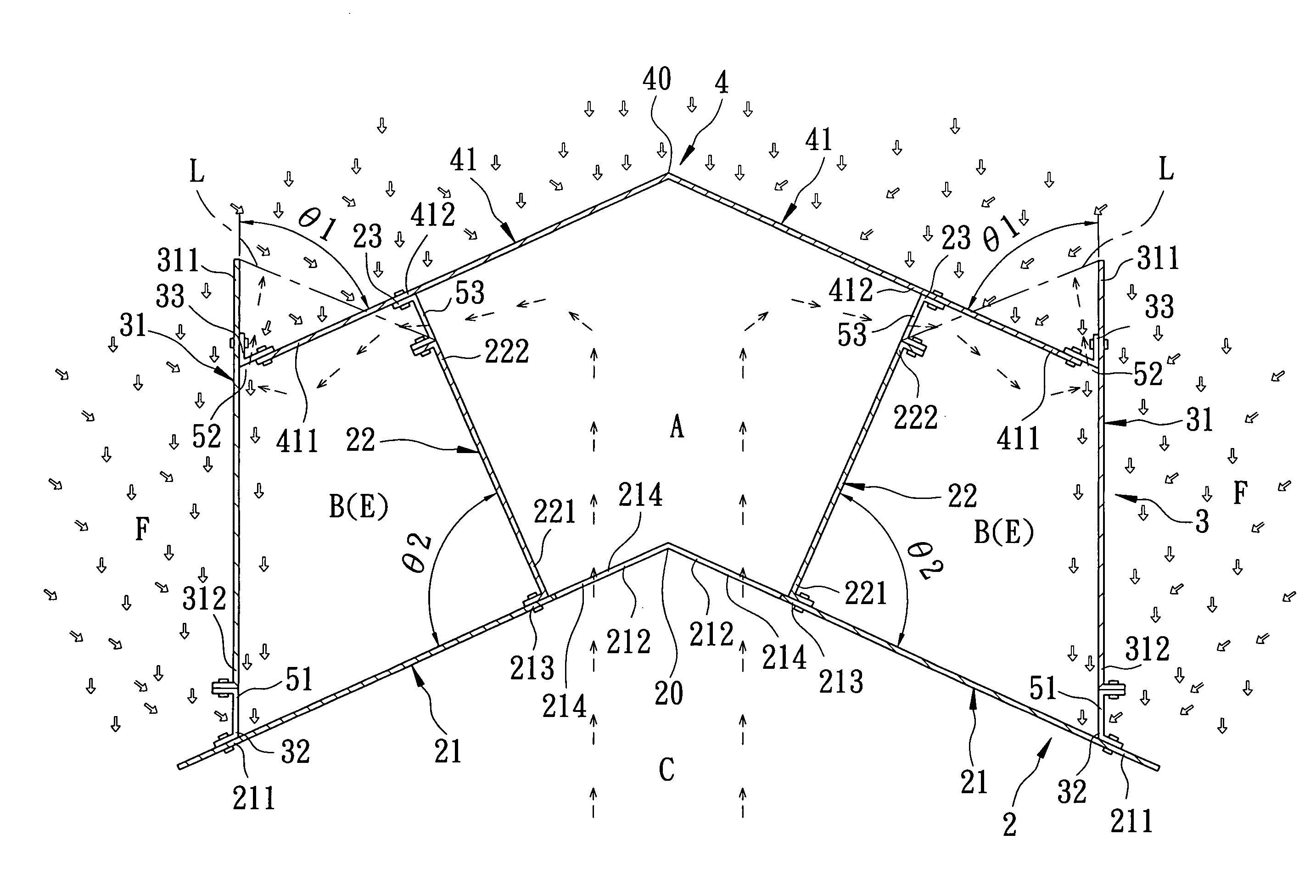
[0018]Referring to FIG. 4, the first preferred embodiment of a ventilated roofing structure according to the present invention is shown to comprise a modular roofing panel unit 4, a wall unit 2, and a modular drainage-route forming panel unit 3.

[0019]In this embodiment, the ventilated roofing structure is formed as an attic that is mounted on top of a building. The modular roofing panel unit 4 is adapted to form part of an outermost layer of a roof, and includes two modular roofing panels 41 which are opposite to each other relative to an outer ridgeline 40 of the roof, which extend outwardly to cover a space thereunder, and which respectively terminate at overhanging eaves 411.

[0020]The wall unit 2 includes two modular first wall panels 22 and two modular second wall panels 21. Each of the first wall p...


PUM


Abstract

A ventilated roofing structure includes a modular roofing panel unit adapted to form part of an outermost layer of a roof, a wall unit which is secured to the roofing panel unit, and which extends downwardly to terminate at an anchored end to partition a space under the roof into outside and inside spaces, and which has a ventilation opening communicating the inside and outside spaces, and a modular drainage-route forming panel unit which is fastened to an overhanging eave of the roofing panel unit to form a gap therebetween. The drainage-route forming panel unit extends downwards to separate the outside space into an airflow transit chamber and an outdoor space, and has an anchoring edge secured to the anchored end, and a drainage port communicating the airflow transit chamber with the outdoor space.

Description

BACKGROUND OF THE INVENTION[0001]1. Field of the Invention[0002]This invention relates to a ventilated roofing structure, more particularly to a naturally ventilated roofing structure.[0003]2. Description of the Related Art[0004]Referring to FIG. 1, a conventional attic ventilation structure 11 is adapted to be mounted on a roof of a building with two base panels 111, and includes two support panels 112 extending upwardly from the base panels 111, and two roof panels 113 respectively fastened to the support panels 112 and spaced apart from the support panels 112 to respectively form two vent ports 115. Thus, heat inside the building can be exhausted out of the building through a ventilation opening 114 formed in the base panels 111 and the vent ports 115 by the combined effect of wind and thermal buoyancy forces. However, rainwater may splatter and enter the building through the vent ports 115, as indicated by hollow arrows in FIG. 1.[0005]Referring to FIG. 2, another conventional v...

Claims


Application Information

Patent Timeline
IPC IPC(8): E04B1/70E04D13/17
CPCE04D13/174
Inventor HUANG, DANIEL C. L.
Owner HUANG DANIEL C L
Why Eureka
Eureka Blog
Learn More